Category: Manuals

d500 nikon manual

The Nikon D500 manual is essential for mastering its advanced features, ensuring optimal performance, and troubleshooting. It provides detailed guidance on camera settings, modes, and troubleshooting, helping users unlock the camera’s full potential. The manual is available in multiple formats, including digital versions and the Nikon Manual Viewer 2 app, making it accessible for all users. Whether you’re a professional or enthusiast, this comprehensive guide is key to maximizing your D500 experience.

Overview of the Nikon D500 Camera

The Nikon D500 is a high-performance DX-format DSLR camera designed for enthusiasts and professionals. It features a 20.9MP APS-C CMOS sensor, EXPEED 5 image processor, and delivers exceptional image quality. With a burst mode of up to 10fps and an expandable ISO range of 100-51,200, it excels in action and low-light photography. The camera supports 4K video recording, utilizes XQD and SD card slots, and boasts a robust, weather-sealed body for durability. Its 153-point autofocus system ensures precise tracking, while the large buffer capacity handles extended shooting sessions effortlessly.

Importance of the User Manual for Optimal Use

The Nikon D500 user manual is crucial for unlocking the camera’s full potential. It provides detailed instructions on navigating menus, customizing controls, and utilizing advanced features like autofocus modes and 4K video recording. The manual also offers troubleshooting tips and explains technical specifications, ensuring users can resolve issues and optimize settings for their photography needs. Available in digital formats and via the Nikon Manual Viewer 2 app, it serves as an essential resource for mastering the D500.

Key Features of the Nikon D500

The Nikon D500 boasts a 20.9MP APS-C sensor, 4K video recording, 10fps burst shooting, and a 153-point autofocus system. Built for speed and durability, it delivers exceptional image quality and performance for both stills and videos, making it a versatile choice for professionals and enthusiasts alike.

Autofocus System and Performance

The Nikon D500 features an advanced 153-point autofocus system, delivering rapid and precise focus acquisition. Its Multi-CAM 20K sensor ensures exceptional tracking and subject detection, even in challenging lighting conditions. The system supports 3D Tracking and Group-Area AF, enabling smooth performance during high-speed or dynamic shooting scenarios. Customizable AF settings further enhance versatility, making it ideal for capturing sharp images in action, wildlife, and portrait photography.

Burst Mode and Buffer Capacity

The Nikon D500 offers an impressive burst mode, capturing up to 10 frames per second with continuous autofocus. Its robust buffer capacity allows for extended shooting sessions, handling up to 200 RAW images or 200 JPEGs in a single burst. This performance makes it ideal for action, sports, and wildlife photography, ensuring you never miss a decisive moment. The buffer clears quickly, minimizing downtime and keeping you ready for the next shot.

ISO Range and Noise Performance

The Nikon D500 features an impressive ISO range of 100 to 51,200, expandable to 50-1,640,000. This wide range ensures excellent performance in various lighting conditions. The camera delivers minimal noise at lower ISOs, and even at higher settings, noise is well-controlled, preserving detail and color accuracy. The EXPEED 5 processor enhances noise reduction, making the D500 suitable for low-light photography. This capability is particularly beneficial for capturing sharp, high-quality images in challenging environments without compromising image integrity.

Video Capabilities and 4K Resolution

The Nikon D500 excels in video recording, offering 4K resolution at 30p and Full HD at 60p. It supports manual focus and exposure control, enhancing creative flexibility. While focus peaking isn’t available, the camera’s EXPEED 5 processor ensures high-quality video output. These features make the D500 a versatile tool for videographers, delivering sharp and detailed footage even in challenging lighting conditions.

Technical Specifications of the Nikon D500

The Nikon D500 features a 20.9MP APS-C CMOS sensor, EXPEED 5 processor, and weighs 860g. It supports ISO 100-51,200, continuous shooting up to 10fps, and 4K video recording, making it a powerful tool for photographers.

Sensor and Image Processor Details

The Nikon D500 features a 20.9MP APS-C CMOS sensor, measuring 23.5×15.7mm, delivering excellent low-light performance and detailed images. The EXPEED 5 image processor enhances speed, noise reduction, and color accuracy, enabling high-quality photos and videos. The sensor’s design supports the camera’s wide ISO range of 100-51,200, expandable to 1,640,000, and facilitates 4K video recording, ensuring versatile and professional-grade image capture capabilities.

ISO Sensitivity and Dynamic Range

The Nikon D500 offers an ISO sensitivity range of 100-51,200, expandable to 1,640,000, ensuring excellent low-light performance. Its wide dynamic range captures rich detail in shadows and highlights, providing professional-grade contrast. The EXPEED 5 processor optimizes noise reduction, delivering clean images even at high ISOs. This capability makes the D500 ideal for diverse lighting conditions, from bright landscapes to indoor events, offering photographers flexibility and reliability in their creative pursuits.

Shutter Speed and Flash Compatibility

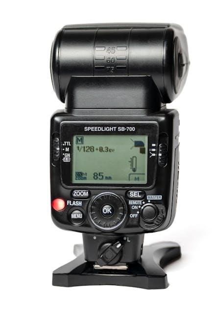
The Nikon D500 offers a wide shutter speed range of 1/8000 to 30 seconds, plus a bulb mode for extended exposures. It supports Nikon’s i-TTL flash system, functioning as both a commander and remote in wireless flash setups. Compatible with various Nikon Speedlights, the D500 enhances lighting control, offering precise illumination for diverse photography scenarios. This flexibility ensures versatile and professional results in both studio and outdoor environments.

Menu Guide and Customization Options

The Nikon D500 menu system is intuitive, allowing users to customize controls and settings efficiently. It also supports wireless connectivity setup for enhanced functionality.

Navigating the Menu System

The Nikon D500 menu system is logically structured and intuitive, allowing users to easily access and customize settings. The menu is divided into color-coded sections, making it simple to locate specific functions. Users can navigate using the multi-selector and OK button, while the manual provides clear guidance for each option; This system enables quick adjustments to autofocus, ISO, and shooting modes, ensuring efficient control over the camera’s advanced features.

Customizing Camera Controls

The Nikon D500 allows users to personalize camera controls to suit their preferences, streamlining workflows. Assign custom functions to buttons like the Fn or AE-L/AF-L buttons for quick access to frequently used settings. The touchscreen also enables intuitive adjustments. By customizing controls, photographers can optimize their shooting experience, ensuring efficient access to critical features during dynamic situations. The manual provides detailed guidance on tailoring these settings for enhanced productivity and creativity.

Setting Up Wireless Connectivity

The Nikon D500 supports Wi-Fi, NFC, and SnapBridge for seamless wireless connectivity. Users can transfer images, control the camera remotely, and sync photos with smart devices. The manual provides step-by-step guidance on enabling these features, configuring network settings, and pairing devices. This functionality enhances workflow efficiency and enables convenient sharing and backup of photos. Wireless connectivity options are detailed in the manual, ensuring users can fully utilize these advanced features.

Shooting Modes and Advanced Functions

The Nikon D500 offers versatile shooting modes, including Manual (M), for precise control over aperture and shutter speed. Advanced functions like bracketing and interval shooting enhance creativity and efficiency, ensuring superior results in various photography scenarios.

Manual Mode (M) and Exposure Control

Manual Mode (M) on the Nikon D500 offers full creative control, allowing users to independently adjust aperture and shutter speed. This mode is ideal for precise exposure management, enabling photographers to achieve desired effects. The D500 also supports bulb mode for long exposures, extending artistic possibilities. With the camera’s intuitive controls, users can easily fine-tune settings to capture professional-quality images. This flexibility makes Manual Mode a favorite among enthusiasts and professionals seeking ultimate control over their photography.

Autofocus Modes and Tracking

The Nikon D500 features advanced autofocus capabilities, including Single AF, Continuous AF, and Dynamic AF modes, powered by 153 focus points. These modes ensure precise and swift subject acquisition, especially in dynamic scenarios like sports or wildlife photography. The camera excels at tracking moving subjects, with customizable focus tracking sensitivity to adapt to various shooting conditions, enhancing overall autofocus performance and versatility for professional and enthusiast photographers alike.

Bracketing and Interval Shooting

The Nikon D500 offers robust bracketing and interval shooting capabilities, ideal for capturing high dynamic range images and time-lapse sequences. The camera supports up to 9-frame exposure bracketing and an adjustable interval timer, allowing for precise control over shooting intervals. These features are particularly useful for landscape, astrophotography, and wildlife photography. The manual provides detailed instructions on setting up and customizing these modes to suit various creative and technical requirements, ensuring optimal results in diverse shooting scenarios.

Video Shooting and Playback

The Nikon D500 supports 4K video recording at 30p and 1080p at 60p, offering versatile frame rates for cinematic and smooth motion capture. Manual focus and exposure control ensure precise video shooting, while playback features allow easy review of recorded footage on the camera’s LCD screen.

4K Video Recording and Frame Rates

The Nikon D500 captures stunning 4K UHD video at 30p, delivering sharp details and vibrant colors. It also supports 1080p Full HD at 60p for smooth motion capture. The camera’s flexible frame rates allow photographers to create cinematic footage or dynamic action sequences. Additionally, manual focus and exposure controls provide precise adjustments during recording, ensuring high-quality video output tailored to creative vision.

Manual Focus and Exposure in Video

The Nikon D500 allows precise manual focus and exposure control during video recording, enabling creative flexibility. Users can adjust aperture, shutter speed, and ISO manually for customized results. While focus peaking isn’t available, manual focus requires skill and patience for sharp footage. Exposure settings can be fine-tuned to match lighting conditions, ensuring professional-grade video output with enhanced control over the visual narrative.

Audio Recording and External Microphone Options

The Nikon D500 supports high-quality audio recording, with options for external microphones to enhance sound capture. It features a built-in monaural microphone and a 3.5mm stereo jack for connecting external mics, such as Nikon’s ME-1 stereo microphone. Manual audio level adjustment ensures precise control over sound quality, making it ideal for professional video production or vlogging. This flexibility allows users to achieve superior audio clarity, complementing the camera’s advanced video capabilities.

Connectivity and Software Integration

The Nikon D500 offers seamless connectivity via Wi-Fi, NFC, and SnapBridge, enabling remote shooting and image transfer. Software integration with Nikon apps enhances workflow and control.

Wi-Fi, NFC, and SnapBridge

The Nikon D500 supports Wi-Fi and NFC for quick connection to smart devices. SnapBridge enables seamless image transfer and remote shooting. The Nikon Manual Viewer 2 app offers easy access to guides, enhancing workflow and control. These features streamline sharing and management, making the D500 versatile for photographers on the go.

Remote Shooting and Image Transfer

The Nikon D500 enables remote shooting and image transfer via Wi-Fi and NFC using SnapBridge. This feature allows photographers to control the camera remotely and transfer images to smart devices automatically. The Nikon Manual Viewer 2 app provides detailed instructions for setting up and using these functions. Remote shooting enhances convenience, while seamless image transfer streamlines workflows, making the D500 ideal for professionals and enthusiasts alike. The manual ensures easy setup and optimal use of these advanced connectivity features.

Using the Nikon Manual Viewer 2 App

The Nikon Manual Viewer 2 app offers a convenient way to access the D500 manual digitally. Available for free on the App Store and Google Play, it provides detailed instructions, tips, and troubleshooting guides. Users can easily navigate through the manual, search for specific features, and bookmark important sections. This app enhances the learning experience, ensuring photographers can fully utilize their D500’s capabilities anytime, anywhere, with offline access for added convenience.

Tips for Getting the Most Out of the Nikon D500

Customize camera controls for personalized shooting experiences and utilize the Nikon Manual Viewer 2 app for easy access to guides and troubleshooting, enhancing your D500 photography skills.

Mastering Autofocus for Action Photography

The Nikon D500 excels in action photography with its advanced autofocus system, offering fast and precise subject tracking. Use continuous AF mode for dynamic scenes and adjust AF-C settings for optimal performance. Leveraging the camera’s 10fps burst mode ensures sharp images of moving subjects. For challenging situations, manual focus or back-button focusing can enhance accuracy. Utilize the Nikon Manual Viewer 2 app for detailed guidance on customizing autofocus settings to match your shooting style.

Optimizing Battery Life and Storage

To maximize the Nikon D500’s battery life, enable power-saving modes and disable unnecessary features like Wi-Fi and GPS. Use the EN-EL15 battery with a 1900 mAh capacity for extended shooting sessions. For storage, utilize high-speed SDXC or XQD cards to handle large files and burst shooting. Regularly format cards to maintain performance and prevent errors. Refer to the Nikon Manual Viewer 2 app for detailed tips on optimizing battery and storage settings for your workflow.

Regular Firmware Updates and Maintenance

Keeping your Nikon D500 up-to-date with the latest firmware ensures optimal performance, bug fixes, and enhanced features. Regularly check Nikon’s official website for updates and follow the manual’s instructions for installation. Proper camera maintenance, such as cleaning the sensor and lens, and updating software, will extend its lifespan. The Nikon Manual Viewer 2 app provides detailed guidance for firmware updates and troubleshooting, ensuring your D500 operates at its best.

The Nikon D500 remains a powerful tool for photographers, offering exceptional performance and versatility. Its advanced features and robust design make it a top choice for enthusiasts and professionals alike. For further learning, Nikon provides extensive resources, including the Manual Viewer 2 app, ensuring users continue to unlock its full potential.

Why the Nikon D500 Remains a Top Choice

The Nikon D500 excels with its robust autofocus, rapid burst mode, and wide ISO range, making it ideal for action and wildlife photography. Its 4K video capabilities and advanced connectivity options further enhance versatility. Coupled with the comprehensive manual and resources like the Nikon Manual Viewer 2 app, the D500 remains a top choice for professionals and enthusiasts seeking reliability and creative control.

Resources for Further Learning

For deeper understanding, the Nikon Manual Viewer 2 app offers interactive guides. Official Nikon websites provide downloadable PDF manuals and detailed technical specifications. Online forums and communities share user experiences and tips. Video tutorials on platforms like YouTube cover advanced techniques. Additionally, Nikon hosts workshops and webinars, while third-party resources like photography blogs and books expand on mastering the D500’s capabilities, ensuring continuous learning and improvement.

black & decker smart battery charger manual

The Black & Decker Smart Battery Charger is a high-frequency, fully automatic device designed for efficient and safe battery charging․ It features advanced smart technology, multiple charge rates, and compatibility with various Black & Decker batteries, ensuring optimal performance and longevity․ This eco-friendly charger is built to deliver reliable service with minimal energy waste, making it a practical choice for users seeking convenience and durability․

1․1 Overview of the Charger and Its Features

The Black & Decker Smart Battery Charger is a high-frequency, fully automatic charger with multiple charging stages and LED indicators for real-time status updates․ It supports various charge rates (40/20/10/4 Amp) to suit different battery types and sizes․ Designed for safety and efficiency, it features advanced smart technology to prevent overcharging and ensure optimal battery health․ The charger is compatible with Black & Decker batteries and is built for eco-friendly performance․

1․2 Importance of Using the Manual for Optimal Performance

Using the manual is crucial for understanding the charger’s operations, safety guidelines, and maintenance tips․ It provides detailed instructions for selecting charge rates, troubleshooting common issues, and ensuring proper battery care․ The manual also highlights safety precautions to prevent hazards, such as incorrect clamp connections or overcharging․ following the manual ensures optimal performance and extends the lifespan of both the charger and battery․

Safety Instructions for Using the Smart Battery Charger

Always disconnect the charger from power and the battery before servicing․ Avoid short circuits and incorrect clamp connections․ Never modify the charger or use it near flammable gases․

2․1 General Safety Precautions

When using the Black & Decker Smart Battery Charger, always ensure the area is well-ventilated to avoid inhaling explosive gases from batteries․ Keep the charger away from children and flammable materials․ Avoid overcharging, as it can damage the battery․ Never attempt to charge a damaged or leaking battery, and always unplug the charger before servicing․ Properly connect the clamps to prevent short circuits and ensure safe operation․

2․2 Proper Disconnecting Procedures

To ensure safe disconnection, always switch off and unplug the charger before removing any connections․ Detach the negative (black) clamp first, followed by the positive (red) clamp․ Never reverse this order to prevent short circuits․ Avoid using regular mains plugs as replacements, and ensure compatibility with only Black & Decker batteries to maintain safety and prevent potential damage or explosions․

2․3 Hazards Associated with Lead-Acid Batteries

Lead-acid batteries pose risks such as toxic lead exposure, corrosive acid leaks, and explosive gases like hydrogen․ Proper handling is crucial to avoid skin and eye contact with acid․ Ventilation is essential to prevent gas accumulation, which can ignite and cause fires or explosions․ Always follow safety guidelines to mitigate these hazards during charging and maintenance․

Key Features of the Black & Decker Smart Battery Charger

The charger features multiple charging stages, high-frequency smart technology, and LED indicators for real-time status updates․ It offers versatile charge rates and compatibility with various batteries, ensuring efficient and safe charging․

3․1 Multiple Charging Stages for Efficient Charging

The Black & Decker Smart Battery Charger utilizes multiple charging stages to optimize efficiency․ It begins with a bulk charge to rapidly replenish battery capacity, followed by an absorption phase to stabilize voltage, and concludes with a float stage to maintain charge without overcharging․ This multi-stage process ensures batteries are charged safely and efficiently, extending their lifespan․

3․2 High-Frequency Smart Charging Technology

The Black & Decker Smart Battery Charger employs high-frequency smart charging technology to enhance charging efficiency and safety․ This advanced system automatically detects battery type and adjusts charging parameters, ensuring optimal performance․ It minimizes energy loss and prevents overheating, providing a reliable and fast charging experience while extending battery life․

3․3 LED Indicators for Charging Status

The Black & Decker Smart Battery Charger features LED indicators that provide real-time updates on charging progress․ These lights display statuses such as charging in progress, fully charged, or error detection․ The LED system ensures users can monitor the charging process effortlessly, offering clear visual feedback to avoid overcharging or operational issues, enhancing overall efficiency and user confidence․

Charge Rate Selection and Settings

The Black & Decker Smart Battery Charger offers multiple charge rates (40/20/10/4 Amp) to suit various battery types and sizes․ Selecting the correct rate ensures efficient charging, with automatic adjustments for optimal performance․ This feature prevents overcharging and extends battery life, making it a versatile solution for different applications and user needs․

4․1 Understanding Different Charge Rates (40/20/10/4 Amp)

The Black & Decker Smart Battery Charger offers four charge rates: 40 Amp, 20 Amp, 10 Amp, and 4 Amp․ These rates cater to different battery sizes and types, ensuring efficient charging․ The 40 Amp rate is ideal for large batteries, while the 4 Amp rate is suitable for smaller ones․ The charger automatically adjusts to the connected battery, preventing overcharging and extending lifespan, making it versatile for various applications․

4․2 How to Select the Correct Charge Rate

Selecting the correct charge rate ensures optimal charging and battery longevity․ Choose the 40 Amp rate for large batteries requiring quick charging, 20 Amp for standard sizes, 10 Amp for smaller batteries, and 4 Amp for maintenance or trickle charging․ Always refer to the battery manufacturer’s recommendations and the charger’s manual to match the rate with your specific battery type and size for safe and efficient charging․

Charging Process and Guidelines

The Black & Decker Smart Battery Charger is a high-frequency, fully automatic device designed for safe and efficient charging․ It works with various Black & Decker batteries and automatically adjusts settings for optimal performance․

5․1 Step-by-Step Guide to Charging a Battery

Connect the charger to a power source and ensure it is turned off․ Attach the positive (red) clamp to the battery’s positive terminal․ Securely connect the negative (black) clamp to the negative terminal or a metal surface․ Turn on the charger and select the appropriate charge rate․ Monitor the LED indicators for charging progress and completion․

5․2 How to Monitor the Charging Progress

Use the LED indicators to monitor charging status․ The charger features color-coded lights: red for charging, amber for maintenance, and green for fully charged․ Ensure the charger is on a stable surface and avoid covering it to maintain proper cooling․ Allow the process to complete without interruption․ Always follow the manufacturer’s guidelines for optimal charging efficiency and safety․

Maintenance and Care Tips

Regularly clean the charger and battery terminals to ensure proper connectivity․ Store in a dry, cool place away from direct sunlight and moisture to maintain efficiency and longevity․

6․1 Cleaning and Storage Recommendations

Use a soft cloth to clean the charger and battery terminals, avoiding harsh chemicals․ Store the charger and batteries in a dry, cool place away from direct sunlight and moisture․ Ensure the area is well-ventilated to prevent hydrogen gas buildup․ Regular cleaning prevents corrosion and ensures reliable performance․ Proper storage extends the lifespan of both the charger and batteries․

6․2 Extending the Lifespan of the Charger and Battery

Avoid extreme temperatures and overcharging to prevent battery degradation․ Store batteries with a 50% charge to maintain health․ Regularly inspect cables and terminals for damage or corrosion․ Use the correct charge rate for your battery type and ensure the charger is updated with the latest software․ Proper care and maintenance will significantly extend the lifespan of both the charger and battery․

Troubleshooting Common Issues

Identify common problems like error lights, slow charging, or no charge․ Check connections, ensure proper clamp placement, and verify the battery type․ Restart the charger or consult the manual for solutions to specific faults or error codes․ Regular maintenance and proper usage can resolve most issues effectively․

7․1 Diagnosing Charging Problems

Diagnose charging issues by checking LED indicators for error codes or unusual behavior․ Ensure clamps are securely connected and free from corrosion․ Verify that the correct charge rate is selected and the battery type matches the charger’s specifications․ If the charger does not turn on, check the power source․ Slow charging may indicate a faulty battery or improper settings․

7․2 Solutions for Common Faults and Errors

For common faults, check if the charger is properly plugged in and the battery is correctly connected․ If error codes appear, refer to the manual for troubleshooting․ Clean corroded clamps and ensure secure connections․ If charging fails, verify the selected charge rate matches the battery type․ Replace fuses or reset circuit breakers if tripped․ If issues persist, contact Black & Decker support for assistance․

Compatibility with Black & Decker Products

The Black & Decker Smart Battery Charger is designed to charge Black & Decker battery packs, ensuring compatibility with drills, vacuums, and other 20V MAX system tools․ It seamlessly integrates with various Black & Decker appliances, providing reliable charging for a wide range of products․ Always check the manual for compatibility․

8․1 List of Compatible Battery Packs

The Black & Decker Smart Battery Charger is compatible with various 20V MAX lithium-ion battery packs, including the 2․0Ah, 4․0Ah, and 5․0Ah models․ It also supports older nickel-cadmium batteries, ensuring versatility across different tool ranges․ For optimal performance, always use genuine Black & Decker battery packs with this charger to maintain reliability and safety․

8․2 Using the Charger with Other Black & Decker Appliances

The Black & Decker Smart Battery Charger is designed to work seamlessly with a wide range of Black & Decker appliances, including drills, lawn mowers, and power tools․ Its universal compatibility ensures effortless switching between devices, while maintaining safety and efficiency․ This versatility makes it a convenient solution for users with multiple Black & Decker products, streamlining their workflow and reducing clutter․

Warranty and Customer Support Information

The Black & Decker Smart Battery Charger is backed by a limited warranty․ For details, visit the official website or contact customer support for assistance and inquiries․

9․1 Warranty Terms and Conditions

The Black & Decker Smart Battery Charger is covered by a limited warranty, which varies by region․ It typically covers defects in materials and workmanship for a specified period․ Registration may be required for warranty activation․ For full details, refer to the product manual or visit the Black & Decker official website․ Terms and conditions apply․

9․2 Contacting Black & Decker Customer Service

For inquiries or assistance, contact Black & Decker customer service via phone, email, or their official website․ Visit their support page for regional contact details and operating hours․ Ensure to have your product model and serial number ready for efficient assistance․ Online resources, FAQs, and downloadable manuals are also available for added convenience․

Environmental Considerations

Properly dispose of batteries and chargers through recycling programs to minimize environmental impact․ The charger is designed with energy efficiency in mind, promoting eco-friendly practices and sustainable use․

10․1 Proper Disposal of Batteries and Chargers

Always recycle batteries and chargers responsibly․ Use designated recycling centers to ensure safe disposal, preventing harmful materials from entering landfills․ Check local regulations for specific guidelines and facilities․ Proper disposal helps protect the environment and conserve natural resources, aligning with eco-friendly practices;

10․2 Energy Efficiency and Eco-Friendly Practices

The Black & Decker Smart Battery Charger is designed with energy efficiency in mind, utilizing high-frequency smart charging technology to minimize energy waste․ It automatically switches to maintenance mode after charging, reducing standby power consumption․ Eco-friendly practices are promoted through efficient charging cycles and durable construction, ensuring long-term performance while supporting environmental responsibility and sustainable energy use․

The Black & Decker Smart Battery Charger offers efficient, safe, and eco-friendly charging solutions․ Always follow manual guidelines, monitor charging progress, and maintain the unit for optimal performance and longevity․

11․1 Summary of Key Takeaways

The Black & Decker Smart Battery Charger is designed for safe and efficient charging․ It features multiple charge rates, high-frequency technology, and compatibility with various batteries․ Always follow safety guidelines, monitor charging progress, and maintain the unit properly․ This eco-friendly charger ensures optimal performance and longevity, making it a reliable choice for users seeking durability and convenience․

11․2 Best Practices for Long-Term Use

Regular maintenance ensures the Black & Decker Smart Battery Charger operates efficiently․ Store it in a dry, cool place, clean terminals regularly, and select the correct charge rate for your battery․ Avoid overcharging and use only compatible Black & Decker batteries․ These practices optimize performance and extend the lifespan of both the charger and battery․

poly voyager 4320 manual

The Poly Voyager 4320 manual is an essential guide for understanding and utilizing your headset’s features, ensuring proper setup, and troubleshooting common issues for optimal performance․

Overview of the Poly Voyager 4320 UC Headset

The Poly Voyager 4320 UC headset is a high-quality, wireless audio solution designed for professionals seeking seamless communication․ It features advanced Bluetooth 5․2 technology, enabling dual-device connectivity and compatibility with PC, Mac, and mobile devices․ The headset offers a robust wireless range of up to 50 meters (164 feet) and an impressive battery life of up to 24 hours, ensuring all-day productivity․ Available in both mono and stereo versions, it caters to diverse user preferences․ With noise-canceling microphones and intuitive controls, the Voyager 4320 UC is built for clear audio and convenient operation․ Its sleek design, lightweight construction, and durable materials make it ideal for office and remote work environments․

Importance of the Manual for Proper Usage

The Poly Voyager 4320 UC manual is crucial for users to unlock the full potential of their headset․ It provides detailed instructions for setup, pairing, and configuration, ensuring a seamless experience․ The manual covers troubleshooting common issues, such as connectivity problems and audio concerns, offering practical solutions to maintain optimal performance․ Additionally, it outlines safety guidelines and compliance information, protecting both the user and the device․ By following the manual, users can customize settings to enhance functionality and take advantage of advanced features like firmware updates․ This comprehensive guide is essential for maximizing the headset’s capabilities and ensuring a hassle-free user experience․

Key Features of the Poly Voyager 4320 UC

The Poly Voyager 4320 UC boasts Bluetooth 5․2 technology, dual-device connectivity, and a 50-meter wireless range, offering enhanced audio quality and extended battery life for seamless productivity․

Bluetooth 5․2 Technology and Dual-Device Connectivity

The Poly Voyager 4320 UC leverages Bluetooth 5․2 technology, ensuring stable and high-speed connections․ With dual-device connectivity, users can simultaneously pair the headset with two devices, such as a computer and smartphone, and remember up to eight devices for effortless switching․ This feature enhances productivity, allowing seamless transitions between calls and audio sources․ The advanced Bluetooth version also reduces interference and provides a more reliable connection, making it ideal for professionals who need uninterrupted communication across multiple platforms․ This capability ensures that the headset remains versatile and accommodating to various work environments and user preferences, promoting efficiency and convenience․

Wireless Range and Battery Life

The Poly Voyager 4320 UC offers an impressive wireless range of up to 50 meters (164 feet) when paired with the included BT700 USB adapter, allowing users to move freely without losing connection․ Its robust battery life ensures up to 24 hours of talk time on a single charge, making it suitable for extended use throughout the day․ Enhanced power management features help conserve energy, while quick charging capabilities provide up to two hours of talk time with just five minutes of charging․ These features collectively ensure uninterrupted productivity, making the headset a reliable choice for professionals requiring consistent, high-performance wireless connectivity and long-lasting battery endurance․

Setting Up the Poly Voyager 4320 UC

Setting up the Poly Voyager 4320 UC involves unboxing, charging, and configuring the headset for seamless connectivity․ Follow the manual for a smooth and straightforward experience․

Connecting the USB Bluetooth Adapter

To connect the USB Bluetooth adapter, insert it into a free USB port on your computer․ Ensure the adapter is properly seated and recognized by your system․ The adapter may require driver installation, which is typically automatic but can be manually downloaded from the Poly website if needed․ Once connected, the adapter enables Bluetooth 5․2 connectivity, allowing pairing with the Poly Voyager 4320 UC headset․ The USB Bluetooth adapter (model BT700 or BT700C) supports up to two device connections and remembers up to eight devices․ It provides a wireless range of up to 50 meters (164 feet) for a seamless audio experience․ The adapter’s LED indicator will confirm successful pairing and connection status;

Pairing the Headset with Your Device

To pair the Poly Voyager 4320 UC headset with your device, slide and hold the Power switch away from the off position until you hear a pairing tone and the LEDs flash red and blue․ This indicates the headset is in pairing mode․ On your device, enable Bluetooth and search for available devices․ Select “Poly BT700” or “Plantronics BT700” from the list․ Once paired, the headset LEDs will stop flashing, confirming the connection․ The headset can connect to two devices simultaneously and remembers up to eight paired devices for easy switching․ Ensure your device is within the 50-meter (164-foot) wireless range for optimal performance․

Advanced Configuration Options

The Poly Voyager 4320 UC offers customizable settings to enhance performance․ Use the Poly Lens Mobile app for onboarding and device tutorials․ Firmware updates ensure optimal functionality and compatibility․

Customizing Settings for Optimal Performance

The Poly Voyager 4320 UC allows users to tailor settings to meet their preferences․ Through the Poly Lens Mobile app, you can adjust audio settings, such as noise cancellation and sound quality, to enhance your experience․ Customizable call controls enable seamless management of calls, while device connectivity options ensure compatibility across multiple platforms․ The headset also supports personalized voice prompts and LED notification settings for better user interaction․ By exploring these configurations, users can optimize performance and create a more intuitive experience․ Regular firmware updates further enhance functionality, ensuring the headset remains up-to-date with the latest features and improvements․ This level of customization empowers users to maximize their productivity and comfort․

Updating Firmware for Enhanced Functionality

Updating the firmware of your Poly Voyager 4320 UC headset ensures access to the latest features, improved performance, and bug fixes․ To update, connect your headset to the Poly Lens Mobile app, which guides you through the process․ The app automatically detects new firmware versions and prompts you to download and install them․ Regular updates are crucial for maintaining optimal functionality and compatibility with your devices․ By keeping your firmware up-to-date, you can enjoy enhanced audio quality, expanded device connectivity options, and improved overall user experience․ This simple process ensures your headset remains current and performs at its best, supporting your productivity and communication needs effectively․

Troubleshooting Common Issues

Troubleshooting your Poly Voyager 4320 UC headset involves diagnosing connectivity, audio, and battery problems․ Use the manual’s step-by-step guides to resolve issues efficiently․

Resolving Connectivity Problems

Connectivity issues with the Poly Voyager 4320 UC can often be resolved by restarting the headset or ensuring the Bluetooth adapter is properly connected․ Check the Bluetooth range, as distance may affect performance․ If pairing fails, slide and hold the Power switch to enter pairing mode until LEDs flash red and blue․ Ensure the USB adapter is correctly plugged into your device and configured in system settings․ For persistent issues, reset the headset by holding the volume down and call button for 15 seconds․ Updating firmware through the Poly Lens Mobile app can also address connection-related bugs․ Always consult the manual for detailed troubleshooting steps to restore a stable connection․

Addressing Audio Quality Concerns

To ensure optimal audio quality with the Poly Voyager 4320 UC, verify that the headset is properly fitted and adjust settings to minimize background noise․ Use the Poly Lens Mobile app to update firmware, as outdated software may cause audio issues․ Check for interference from nearby devices and ensure the Bluetooth connection is stable․ If audio is unclear, reset the headset by holding the volume down and call button for 15 seconds․ For persistent issues, consult the manual for advanced troubleshooting steps, such as adjusting microphone sensitivity or enabling noise cancellation features․ Regularly updating settings and ensuring proper device pairing can significantly enhance call clarity and overall audio performance․ Always refer to the manual for detailed guidance on resolving specific audio concerns․

The Poly Voyager 4320 manual provides comprehensive guidance to enhance your headset experience, ensuring proper setup, troubleshooting, and customization for optimal performance and functionality․

Maximizing the Potential of the Poly Voyager 4320 UC

To fully utilize the Poly Voyager 4320 UC, explore its advanced features like Bluetooth 5․2 for stable connections and dual-device pairing․ Regular firmware updates ensure optimal performance and access to new functionalities․ Customize settings through the companion app to tailor the headset to your preferences, such as adjusting audio settings or enabling voice prompts․ Additionally, leveraging the headset’s long battery life and extensive wireless range allows for uninterrupted productivity․ By following the manual’s guidance, users can unlock all capabilities, ensuring a seamless and efficient experience across various professional environments․

Resources for Further Assistance

For additional support, visit the official Poly website, which offers comprehensive guides, firmware updates, and troubleshooting tips․ The Poly Lens Mobile app provides onboarding instructions and device tutorials․ Download the Poly Voyager 4320 UC User Manual or Quick Start Guide for detailed instructions․ Explore the knowledge library on Poly’s support page for answers to common questions․ Contact Poly’s customer support for personalized assistance․ Ensure to register your device for warranty and updates․ These resources empower users to resolve issues and maximize their headset’s functionality, ensuring a seamless experience with the Poly Voyager 4320 UC․

bosch silence plus 46 dba manual

Welcome to the Bosch Silence Plus 46 dBa manual, your comprehensive guide to understanding and optimizing your ultra-quiet, energy-efficient dishwasher for exceptional cleaning results and longevity.

1.1 Overview of the Bosch Silence Plus Dishwasher

The Bosch Silence Plus 46 dBa dishwasher is a high-performance, ultra-quiet appliance designed for efficient and superior cleaning. With an exceptional noise level of 46 dBa, it operates almost silently, making it ideal for modern kitchens. This model combines energy efficiency, eco-friendly features, and advanced washing cycles to deliver spotless results. Its sleek design and innovative technology ensure optimal performance while maintaining low energy consumption. Perfect for homeowners seeking a reliable, quiet, and eco-conscious dishwasher, the Bosch Silence Plus 46 dBa is a top choice for everyday use.

1.2 Importance of the Manual for Optimal Usage

The Bosch Silence Plus 46 dBa manual is a vital resource for ensuring safe, efficient, and effective use of your dishwasher. It provides detailed instructions for installation, operation, and maintenance, helping you avoid potential issues and extend the appliance’s lifespan. By following the guidelines, you can troubleshoot common problems, understand error codes, and optimize performance. Regular maintenance tips, such as cleaning filters and checking water flow, are also highlighted to keep your dishwasher running smoothly. This manual is essential for maximizing functionality and enjoying a seamless user experience.

Key Features and Benefits of Bosch Silence Plus 46 dBa

The Bosch Silence Plus 46 dBa offers ultra-quiet operation, superior energy efficiency, and advanced wash cycles, ensuring a premium dishwashing experience with minimal noise and maximum efficiency.

2.1 Exceptional Noise Level of 46 dBa

The Bosch Silence Plus 46 dBa dishwasher operates at an incredibly quiet noise level, making it ideal for households that value peace and tranquility during operation. This ultra-low sound output ensures minimal disruption to daily life, whether running a cycle during the day or overnight. The advanced noise-reduction technology minimizes vibrations and operational sounds, providing a seamless and unobtrusive cleaning experience. This feature is particularly beneficial for open-plan living spaces or homes where noise levels are a priority, allowing users to enjoy a quieter kitchen environment while maintaining superior cleaning performance.

2.2 Energy Efficiency and Eco-Friendliness

The Bosch Silence Plus 46 dBa dishwasher is designed with energy efficiency in mind, offering eco-friendly features that reduce energy and water consumption. Its advanced sensors optimize water usage and temperature control, ensuring minimal waste. The Eco Cycle is specifically tailored for energy-saving performance, while the Energy Star certification confirms its environmental benefits. By combining quiet operation with sustainable design, this dishwasher aligns with modern eco-conscious lifestyles, helping users save resources while maintaining superior cleaning results. Bosch’s commitment to innovation ensures this appliance is both efficient and environmentally responsible.

2.3 Advanced Washing Cycles and Options

The Bosch Silence Plus 46 dBa dishwasher offers a wide range of advanced washing cycles tailored to meet diverse cleaning needs. From the Heavy Duty cycle for heavily soiled dishes to the Express Wash for quick results, each option is designed to deliver exceptional cleaning performance. Additional features include adjustable temperature settings, water pressure control, and eco-mode for energy-saving operation. The dishwasher also supports smart customization via Home Connect, enabling users to adapt cycles to their preferences. These advanced options ensure sparkling clean dishes while maintaining energy efficiency and quiet operation.

Installation and Setup Guidelines

Ensure proper installation by following pre-installation requirements and step-by-step instructions for a seamless setup. Connect to Home Connect for smart features and optimal performance. This section guides you through the process, ensuring your Bosch Silence Plus dishwasher operates smoothly from day one.

3.1 Pre-Installation Requirements

Before installing your Bosch Silence Plus 46 dBa dishwasher, ensure the space meets specific requirements. The area must be level, well-ventilated, and have access to water and power supplies. Ensure the power supply matches the dishwasher’s specifications, and water connections are compatible with the provided hoses. Additionally, review the installation manual to confirm all safety guidelines, such as disconnecting from the power grid during installation. Proper preparation ensures a smooth and safe setup process for your appliance.

3.2 Step-by-Step Installation Instructions

  1. Ensure the installation site is level and clear of obstructions.
  2. Place the dishwasher in the desired location, ensuring it is disconnected from power.
  3. Connect the water supply lines securely to prevent leaks.
  4. Install the drainage hose correctly, ensuring proper venting and flow.
  5. Secure the appliance to adjacent surfaces to prevent movement during operation.
  6. Reconnect power and test the dishwasher to ensure all functions operate smoothly.

Follow these steps carefully for safe and proper installation of your Bosch Silence Plus dishwasher.

3.3 Connecting to Home Connect for Smart Features

To connect your Bosch Silence Plus 46 dBa dishwasher to Home Connect, download the Home Connect app and follow in-app instructions. Ensure your dishwasher is compatible and Wi-Fi enabled. Reset the Wi-Fi or Bluetooth connection if pairing fails. Once connected, control and monitor your dishwasher remotely, receive notifications, and access smart features like voice control and customized settings for enhanced convenience and efficiency. Troubleshooting tips are available in the manual for smooth integration and optimal smart functionality.

Operating the Bosch Silence Plus 46 dBa

Learn to navigate the control panel, load dishes efficiently, and select optimal wash cycles for superior cleaning results and tailored performance to meet your specific needs.

4.1 Understanding the Control Panel and Settings

The Bosch Silence Plus 46 dBa control panel features intuitive buttons for cycle selection, intensity adjustment, and drying options. The LCD display shows current settings and error codes. Key buttons include Start/Stop, Delay Start, and Options for customizing wash cycles. Use the Intensity button to adjust water pressure and the Dry button for enhanced drying. Indicator lights signal when salt or rinse aid levels are low. Familiarize yourself with error codes like E1 or E2 to diagnose issues quickly. Regularly check the panel for updates or alerts to ensure optimal performance.

4.2 Loading the Dishwasher for Maximum Efficiency

Proper loading is key to maximizing cleaning efficiency. Arrange dishes facing the center, with larger items at the bottom and lighter ones on top. Use the tines and racks effectively to prevent overcrowding. Ensure utensils are placed in designated holders, facing the correct direction. Avoid blocking the water jets or spray arms, as this hampers water circulation. Secure fragile items in safe positions to prevent breakage. Regularly check the manual for specific loading tips tailored to your Bosch Silence Plus 46 dBa model for optimal performance and cleaner dishes.

4.3 Selecting the Right Wash Cycle

Selecting the right wash cycle on your Bosch Silence Plus 46 dBa ensures optimal cleaning while saving energy and time. Choose from options like “Speed Perfect” for faster cycles or “Eco” for energy efficiency; For heavily soiled dishes, the “Heavy Duty” cycle is ideal. Use the “Normal” cycle for everyday cleaning. Always pre-rinse heavily soiled items and check dish labels for specific washing recommendations. This ensures your dishes come out spotless while maintaining the appliance’s performance and longevity.

Maintenance and Cleaning Tips

Regularly clean the filter and spray arms to ensure optimal performance. Check and clear blockages in the pump for proper drainage. Use Bosch-recommended cleaners for maintenance cycles.

5.1 Regular Cleaning of the Filter and Spray Arms

Regular cleaning of the filter and spray arms is essential for maintaining your Bosch Silence Plus 46 dBa dishwasher’s performance. Start by locating and removing the filter at the bottom of the dishwasher. Rinse it under warm water to eliminate food particles. For spray arms, check for blockages and clean out any debris using a toothbrush. Soak parts in warm soapy water if heavily clogged. Reassemble everything securely to ensure proper water flow. This routine prevents poor washing results and extends the appliance’s lifespan, keeping it running efficiently and quietly.

5;2 Running Cleaning Cycles for Optimal Performance

Regularly running cleaning cycles ensures your Bosch Silence Plus 46 dBa dishwasher operates efficiently. Use Bosch’s recommended cleaner for optimal results. Select the “Cleaning Cycle” or “Maintenance Wash” option on the control panel. Ensure the dishwasher is empty and follow the cycle’s instructions. This process removes grease and food residue, preventing buildup and maintaining performance. Run a cleaning cycle every 1-2 months, depending on usage. This routine helps prevent odors and ensures your dishwasher continues to deliver spotless results. Always refer to your manual for specific cycle details and guidelines.

Troubleshooting Common Issues

Identify and resolve common problems like error codes, drainage issues, or operational delays by checking filters, ensuring proper installation, and referring to the manual for solutions.

6.1 Diagnosing Error Codes and Alarms

Recognizing error codes and alarms is crucial for troubleshooting your Bosch Silence Plus 46 dBa dishwasher. Common issues include blocked filters or drainage problems, often indicated by blinking lights or beeps. Refer to the manual for specific code meanings, such as “E1” for water inlet issues or “E2” for drainage faults. Ensure the appliance is installed correctly and restart it after resolving the issue. Regular maintenance, like cleaning filters, can prevent recurring errors and maintain optimal performance. Always consult the manual for detailed diagnostics and solutions.

6;2 Resolving Drainage and Water Flow Problems

Drainage issues can often be resolved by cleaning the filter unit and checking the pump for blockages. Ensure the dishwasher is installed correctly, with the drain hose properly secured and elevated to prevent backflow. Regularly inspect and clean the spray arms to maintain water flow efficiency. If problems persist, consult the troubleshooting section or contact Bosch support for further assistance. Always refer to the manual for specific guidance on diagnosing and resolving drainage-related errors.

Your Bosch Silence Plus 46 dBa dishwasher offers quiet efficiency and superior cleaning. Follow the manual for optimal performance, and regular maintenance ensures long-lasting reliability and hygiene.

7.1 Summary of Key Points

The Bosch Silence Plus 46 dBa manual provides essential insights into optimizing your dishwasher’s performance. Key features include its ultra-quiet operation, energy efficiency, and advanced wash cycles. Regular maintenance, such as cleaning filters and running cleaning cycles, ensures longevity. Troubleshooting tips help resolve common issues like drainage problems and error codes. By following the manual’s guidelines, you can maximize efficiency, reduce noise, and extend the appliance’s lifespan. Proper installation, smart connectivity, and adherence to safety instructions are also highlighted for a seamless user experience.

7.2 Final Tips for Extended Appliance Longevity

Regularly clean the filter and spray arms to ensure optimal water flow and prevent blockages. Run cleaning cycles periodically to maintain performance and hygiene. Avoid using abrasive cleaners that could damage surfaces. Always use dishwasher-specific detergents to prevent residue buildup. Check for blockages in the drain hose and ensure proper installation. Refer to the manual for specific maintenance recommendations tailored to your Bosch Silence Plus 46 dBa model. By following these tips, you can extend the lifespan of your appliance and ensure it continues to deliver exceptional results.

ge over the range microwave manual

Welcome to the GE Over-the-Range Microwave Manual! This guide provides essential information for safe operation, features, and troubleshooting to ensure optimal performance and longevity of your appliance.

1.1 Purpose and Content of the Manual

This manual is designed to guide users in safely operating and maintaining their GE Over-the-Range Microwave. It includes essential safety precautions, installation requirements, and detailed instructions for using advanced features. The manual also provides troubleshooting tips, maintenance recommendations, and warranty information to ensure optimal performance and longevity of the appliance. By following the guidelines outlined in this manual, users can maximize their microwave’s efficiency and enjoy a seamless cooking experience.

1.2 Important Safety Instructions

  • Always ground the microwave to prevent electric shock.
  • Ensure proper ventilation by installing over ranges up to 36″ wide.
  • Avoid installing near flammable materials or heat sources.
  • Keep children away from the microwave while it’s in operation.
  • Do not modify the microwave or use it for storage.
  • Use only microwave-safe utensils to prevent fires.

1.3 Model Identification and Serial Number

Your GE Over-the-Range Microwave’s model and serial number are essential for registration, repairs, and warranty claims. Locate these details on the rating plate, typically found on the top or side of the unit or behind the grille. Record the model number (e.g., JVM3160RFSS) and serial number (e.g., 123456GB) for future reference. These identifiers ensure compatibility with accessories and provide specific information for customer support or service requests.

Safety Precautions and Warnings

Always read and follow the manual to ensure safe operation. Avoid using metal utensils, keep children away, and never heat flammable or explosive items. Proper ventilation is crucial.

2.1 General Safety Guidelines

Read all instructions carefully before using your GE Over-the-Range Microwave. Avoid using metal utensils or flammable materials inside. Keep children away during operation. Ensure proper ventilation and never heat explosive or flammable items. Always follow recommended cooking times and power levels. Unplug the appliance during cleaning or maintenance. Avoid overheating foods, as this can cause burns or fires. Ensure the microwave is installed and grounded correctly by a qualified technician. Regularly inspect for damage and ensure all safety features are functioning properly;

2.2 Electrical Safety Instructions

Ensure the microwave is properly grounded to avoid electric shock. A qualified electrician should perform a ground continuity check on the wall receptacle before installation. The appliance must be installed according to local electrical codes and safety standards. Never modify the power cord or use an incorrect voltage supply. Avoid exposing electrical components to moisture. Keep the power cord away from hot surfaces and sharp edges. Always unplug the microwave before servicing or cleaning. Follow these guidelines to ensure safe and reliable operation of your GE Over-the-Range Microwave.

2.3 Ventilation Requirements

Proper ventilation is crucial for safe and efficient operation of your GE Over-the-Range Microwave. Ensure the unit is installed with adequate airflow to prevent moisture buildup and reduce cooking odors. The microwave must be vented either through an external duct or recirculated using a suitable venting kit. For models with top venting holes, avoid blocking airflow with cabinetry. Follow GE’s guidelines for venting configurations to maintain performance and prevent potential damage. Proper ventilation ensures optimal functionality and longevity of your appliance.

Installation Instructions

Proper installation ensures safe and efficient operation. Follow GE’s guidelines, requiring basic mechanical and electrical skills. The unit must be installed over ranges with adequate ventilation and proper grounding to meet safety standards.

3.1 Pre-Installation Requirements

  • Ensure the installation location is suitable for the microwave, avoiding direct sunlight or moisture exposure.
  • Verify cabinet dimensions and surrounding space meet GE’s specified clearance requirements for proper ventilation.
  • Check electrical connections, ensuring a dedicated 120V outlet is available and grounded properly.
  • Confirm the range below the microwave does not exceed 36 inches in width for compatibility.
  • Review and use the installation templates provided with the unit for accurate mounting.

3.2 Venting Options and Configurations

GE over-the-range microwaves offer flexible venting options to suit various kitchen setups. Choose from recirculating ventilation, which filters air and circulates it back into the kitchen, or external venting, which exhausts air outside through a duct. Vertical or horizontal ducting configurations are available, depending on your home’s layout. Ensure proper venting to maintain efficiency and safety. Refer to your specific model’s manual for detailed venting requirements, as configurations may vary. Always follow manufacturer guidelines for optimal performance and compliance with safety standards.

3.3 Clearance Specifications and Measurements

Proper clearance is essential for safe and efficient installation of your GE over-the-range microwave. Ensure at least 12 inches of clearance above the range and 3 inches on either side of the unit. Maximum cabinet depth above the microwave should not exceed 13 inches to maintain proper airflow and avoid obstruction. Always follow the manufacturer’s guidelines for specific model measurements, as variations may apply. Correct clearance ensures safe operation and compliance with installation standards.

Key Features and Controls

Explore advanced features like sensor cooking, preset options, and LED lighting. The intuitive control panel offers easy navigation for optimal cooking performance and personalized settings.

4.1 Overview of the Control Panel

The control panel features a user-friendly interface with touch-sensitive buttons, including options for cooking modes, power levels, and ventilation. Key controls include the Start/Stop button, cooking time adjustment, and preset functions like defrosting and reheating. The panel also includes indicators for ventilation speed and cooking status. Some models offer advanced features such as a MyPlate button for quick access to healthy cooking options and sensor cooking to automatically adjust cooking times based on food moisture levels.

4.2 Special Cooking Modes and Sensors

GE microwaves offer advanced cooking modes, including sensor cooking that automatically adjusts cooking time based on food moisture. Special modes like defrosting, reheating, and MyPlate simplify cooking for specific tasks. Sensors monitor food and adjust power levels to prevent overcooking, ensuring optimal results. Select models feature smart cooking options that sync with Bluetooth-enabled range hoods, enhancing kitchen convenience and efficiency. These features make cooking easier and more precise, catering to various culinary needs.

4.3 Lighting and Ventilation Systems

GE over-the-range microwaves feature superior lighting and ventilation systems for enhanced cooking experiences. LED lighting provides bright, even illumination over your cooktop, while multiple ventilation settings ensure efficient air circulation. Models offer recirculating or external venting options, with some syncing automatically with Bluetooth-enabled range hoods. Proper installation and maintenance of these systems are crucial for optimal performance. Refer to the manual for specific ventilation configurations and cleaning tips to keep your kitchen fresh and smoke-free during cooking.

Cooking and Defrosting Guide

This section provides essential cooking and defrosting tips, including preset options, sensor cooking, and defrosting guidelines. Use microwave-safe utensils and follow manual instructions for safe, efficient results;

5.1 Recommended Cooking Utensils

Use microwave-safe glass, ceramic, or plastic containers. Avoid metal or aluminum foil, as they can cause sparks or arcing. Ensure utensils are labeled “microwave-safe” to prevent damage or fire hazards. For defrosting, use covered containers to retain moisture and promote even thawing. Always check for cracks or chips in dishes before microwaving to avoid breakage. Follow the manual’s guidelines for specific utensil recommendations to ensure safe and efficient cooking results with your GE microwave.

5.2 Defrosting and Reheating Guidelines

Always cover food with a microwave-safe lid or plastic wrap to retain moisture. Check food every 30 seconds to avoid overcooking. Use the defrost setting for even thawing, and let food stand for 1-2 minutes after defrosting. For reheating, set power levels between 30-50% to prevent drying out. Ensure food is at room temperature before microwaving for consistent results. Follow the manual’s specific defrosting and reheating charts for precise cooking times and power levels based on food type and quantity.

5.3 Preset Cooking Options and Settings

Your GE over-the-range microwave features preset cooking options for common foods like popcorn, baked potatoes, and frozen vegetables. Use the sensor cooking mode to automatically adjust cooking time and power levels. The MyPlate button simplifies cooking for healthy portions. For frozen meals, select the frozen dinner setting for even heating. Adjust power levels between 10%-100% for customized cooking. Refer to the control panel or manual for specific preset options and settings to achieve perfect results every time.

Maintenance and Troubleshooting

Regularly clean the microwave interior and filters to maintain performance. Troubleshoot common issues like uneven heating or error codes by checking for blockages or power supply problems;

6.1 Cleaning and Care Tips

Regular cleaning is essential for maintaining your GE over-the-range microwave’s performance. Wipe the interior with a damp cloth after each use to prevent food residue buildup. For tougher stains, mix baking soda and water to create a paste, apply it, and let it sit before rinsing. Avoid using abrasive cleaners or metal scrubbers, as they may damage surfaces. Clean the turntable and supports with mild detergent and warm water. For exterior surfaces, use a soft cloth and a gentle cleaner. Replace filters as recommended to ensure proper ventilation.

6.2 Common Issues and Solutions

If your GE over-the-range microwave is not heating, check the power supply and ensure the door is closed properly. For uneven cooking, adjust cooking times or rotate dishes. If noise occurs, ensure the turntable is clean and properly aligned. Ventilation issues may arise if filters are clogged; clean or replace them as needed. For error codes, consult the manual or reset the microwave by unplugging it for 30 seconds. Always refer to the troubleshooting guide for specific solutions to maintain optimal performance.

6.3 Filter Replacement and Upkeep

Regularly clean or replace your microwave’s filters to maintain proper ventilation and performance. Clean grease filters with soapy water and dry thoroughly before reinstalling. Charcoal filters, if applicable, cannot be cleaned and should be replaced every 6-12 months. Ensure vents are unobstructed to prevent poor airflow. Replace damaged or worn-out filters promptly. Refer to your manual for specific instructions tailored to your model, such as JVM3160RFSS, to ensure proper upkeep and maintain your microwave’s efficiency and longevity.

Warranty and Customer Support

GE offers comprehensive warranty coverage and dedicated customer support. Visit GEAppliances.com for detailed warranty terms, or call 1-800-626-2000 for assistance with your model, such as JVM3160RFSS.

7.1 Warranty Coverage and Terms

GE offers a comprehensive warranty for your over-the-range microwave, covering parts and labor for one year from purchase. Extended warranties may be available for additional coverage. Register your appliance on GEAppliances.com to validate your warranty. For questions or claims, contact GE’s customer support at 1-800-626-2000. Always refer to your model-specific manual, like JVM3160RFSS, for detailed terms and conditions.

7.2 Contact Information for Support

For assistance, visit GEAppliances.com or call the GE Answer Center at 1-800-626-2000. Support is available to address questions, repairs, or warranty inquiries. You can also register your appliance or access online resources through the website. For technical support or troubleshooting, refer to your model-specific manual, such as JVM3160RFSS, for detailed contact information and guidelines.

7.3 Online Resources and Manuals

Visit GEAppliances.com for comprehensive online resources, including downloadable manuals, troubleshooting guides, and warranty information. Enter your microwave’s model number in the search bar to access specific documentation. For models like JVM3160RFSS or JNM3163RJ3SS, detailed manuals are available in PDF format. Additionally, the website offers user-friendly guides for installation, maintenance, and operation, ensuring you get the most out of your GE Over-the-Range Microwave.

john deere 333g service manual

Welcome to the John Deere 333G Service Manual, your comprehensive guide for operating, maintaining, and repairing the 333G Compact Track Loader. This manual covers essential procedures, diagnostic tools, and repair tips to ensure optimal performance and longevity of your equipment. Designed for operators and technicians, it provides detailed instructions and safety guidelines to help you service your machine effectively. Discover how to maximize efficiency and safety with this official resource.

Overview of the John Deere 333G Compact Track Loader

The John Deere 333G Compact Track Loader is a high-performance machine designed for versatility and ease of operation. Built for demanding applications, it combines power, precision, and comfort, making it ideal for construction, landscaping, and agricultural tasks. Its compact design and robust construction ensure durability and reliability. The 333G features advanced controls and ergonomic design for operator comfort. This loader is supported by comprehensive service manuals, ensuring proper maintenance and troubleshooting for optimal performance and longevity.

Importance of Using the Official Service Manual

Using the official John Deere 333G Service Manual ensures accuracy, safety, and compliance with manufacturer standards. It provides detailed procedures for maintenance, diagnostics, and repairs, reducing the risk of errors. The manual includes genuine parts information, torque specifications, and troubleshooting guides, essential for maintaining equipment performance. Following the official manual guarantees reliability and extends the lifespan of your Compact Track Loader, while also ensuring operator safety and adherence to warranty requirements.

Operation and Test Services

This section guides operators through essential checks and tests to ensure the John Deere 333G operates safely and efficiently, covering pre-start inspections and diagnostic procedures.

Pre-Start Walk-Around and Daily Service Checks

The pre-start walk-around ensures the John Deere 333G is ready for operation by inspecting tires, tracks, and hydraulic systems. Daily service checks include verifying fluid levels, battery condition, and control functions. Ensure all safety features are operational and address any leaks or damage promptly. Following these routines helps prevent unexpected downtime and maintains machine performance. Always refer to the official manual for detailed inspection guidelines and procedures.

Operational Tests and Diagnostic Procedures

Conduct operational tests to ensure the John Deere 333G functions properly. Check hydraulic system performance, control responsiveness, and monitor for error codes. Use diagnostic tools to identify issues and refer to the manual for troubleshooting steps. Test all systems under load to verify functionality. Regular diagnostic checks help detect potential problems early, preventing unexpected downtime. Always follow safety guidelines during testing and address any issues promptly to maintain machine reliability and performance.

Maintenance and Service Schedule

Regular maintenance is crucial for optimal performance and longevity. Follow recommended intervals for checking fluids, filters, and wear components. Schedule services to ensure reliability and minimize downtime.

Recommended Maintenance Intervals

Regular maintenance is essential to ensure the John Deere 333G Compact Track Loader operates efficiently; Follow the recommended service intervals outlined in the manual, such as daily checks for fluid levels, hydraulic system inspections, and track wear monitoring. Replace filters and lubricants at specified intervals to prevent premature wear. Schedule periodic inspections of belts, hoses, and cooling systems to maintain performance and extend equipment lifespan. Adhering to these intervals helps prevent unexpected issues and ensures reliable operation.

Fluid and Filter Replacement Guidelines

Regular fluid and filter replacements are crucial for maintaining the John Deere 333G’s performance. The manual specifies intervals for hydraulic fluid, engine oil, and coolant changes. Always use genuine John Deere filters to ensure compatibility and efficiency. Refer to the torque specifications for drain plugs and filter installations. Proper disposal of used fluids and filters is essential to comply with environmental regulations. Follow these guidelines to maintain optimal machine functionality and extend its service life.

Diagnostic and Troubleshooting

The John Deere 333G Service Manual provides diagnostic procedures to identify and resolve issues efficiently. Use diagnostic codes and tests for accurate troubleshooting, ensuring optimal performance with genuine parts.

Common Issues and Diagnostic Codes

The John Deere 333G Service Manual identifies common issues like hydraulic system errors, engine performance problems, and track system malfunctions. Diagnostic codes provide specific insights, enabling quick identification of faulty components. For instance, error codes for hydraulic pressure or temperature fluctuations guide technicians to potential issues. The manual also offers step-by-step troubleshooting procedures and repair tips, ensuring efficient resolution. Always refer to genuine John Deere parts for replacements to maintain machine integrity and safety.

Troubleshooting Techniques and Repair Tips

The John Deere 333G Service Manual provides detailed troubleshooting techniques to address common issues efficiently. Techniques include checking diagnostic codes, inspecting hydraulic lines for leaks, and testing electrical connections. Repair tips emphasize the importance of using genuine John Deere parts and adhering to torque specifications. Regular lubrication of moving parts and timely track adjustments are also highlighted to prevent wear. These guidelines help minimize downtime and ensure safe, effective repairs.

Repair and Replacement Procedures

The manual provides step-by-step repair instructions, including torque specifications and tool requirements. Detailed guidance ensures safe and effective replacements, minimizing downtime and maintaining performance.

Step-by-Step Repair Instructions

The John Deere 333G Service Manual offers detailed, step-by-step repair instructions to guide technicians through complex procedures. From disassembly to reassembly, each process is clearly outlined with high-quality images and diagrams. Troubleshooting sections help identify issues quickly, while repair tips ensure fixes are done right the first time. Whether addressing hydraulic systems, engine components, or track maintenance, the manual provides precise guidance for efficient and safe repairs, minimizing downtime and extending equipment life.

Torque Specifications and Tool Requirements

The John Deere 333G Service Manual provides precise torque specifications for bolts, nuts, and other components to ensure proper assembly and prevent damage. It lists essential tools required for repairs, such as torque wrenches, impact sockets, and hydraulic pressure testers. Detailed diagrams guide technicians through critical procedures, emphasizing the importance of adhering to specifications for reliability and safety. This section is crucial for maintaining the integrity of your Compact Track Loader during repairs or maintenance.

Parts and Accessories

This section provides detailed information on genuine John Deere parts and accessories for the 333G Compact Track Loader, ensuring compatibility and optimal performance for your machine.

Parts Catalog and Compatibility

The John Deere 333G Service Manual includes a detailed parts catalog, ensuring compatibility with your Compact Track Loader. It lists specific part numbers, diagrams, and descriptions for accurate identification. Compatibility is guaranteed for models like the 331G and 333G, covering components such as tracks, engines, and hydraulic systems. Torque specifications and tool requirements are also provided to ensure proper installation and maintenance. Using genuine John Deere parts ensures reliability and maintains your machine’s warranty.

How to Order Genuine John Deere Parts

To order genuine John Deere parts for your 333G Compact Track Loader, refer to the parts catalog in the service manual. Use the specific part numbers and descriptions provided to ensure compatibility. Visit the official John Deere website or contact an authorized dealer to place your order. Genuine parts guarantee optimal performance, safety, and warranty compliance. Always verify part numbers and quantities before purchasing to avoid errors.

Safety Guidelines and Precautions

Always wear protective gear and follow safety measures when servicing the John Deere 333G. Ensure the machine is stabilized and powered off before starting repairs. Adhere to proper handling of hazardous materials to prevent accidents and environmental contamination. Refer to the official manual for detailed safety protocols to ensure a secure working environment and compliance with safety standards.

Safety Measures During Maintenance and Repair

Always disconnect the battery and ensure the machine is securely stabilized before performing maintenance. Use jack stands for added safety and wear protective gear, including gloves and safety glasses. Follow proper lockout/tagout procedures to prevent accidental start-ups. Ensure good ventilation when working with hazardous materials, and dispose of waste according to environmental regulations. Refer to the manual for specific safety protocols and use approved tools to avoid injuries. Never bypass safety features or skip precautions to ensure a safe working environment.

Handling Hazardous Materials and Waste

When handling hazardous materials, wear appropriate PPE, including gloves and goggles. Dispose of fluids like hydraulic oil and coolant according to environmental regulations. Batteries and other toxic components must be recycled properly. Use spill kits to contain leaks and prevent contamination. Ensure all waste is labeled and stored securely before disposal. Always consult local authorities for specific guidelines on hazardous waste management to maintain compliance and safety standards. Proper disposal protects both the environment and personnel.

The John Deere 333G Service Manual is an essential resource for maintaining and repairing your equipment. It ensures optimal performance, safety, and longevity, guiding you effectively.

Final Thoughts on Using the Service Manual

Using the John Deere 333G Service Manual is crucial for maintaining your equipment’s performance and longevity. It provides detailed guidance for diagnostics, repairs, and maintenance, ensuring safety and efficiency. By following the manual’s instructions, you can prevent costly repairs and extend the life of your Compact Track Loader. Always refer to this official resource for accurate information and adhere to the recommended procedures. Regularly consulting the manual will help you optimize your machine’s operation and ensure compliance with safety standards, making it an indispensable tool for both operators and technicians.

Resources for Further Assistance

For additional support, visit the official John Deere website to download the latest service manuals and parts catalogs. The John Deere 333G Compact Track Loader Operation and Diagnostic Test Technical Service Manual (TM14062X19) is available as a PDF, offering detailed instructions and diagrams. You can also access instructional DVDs for pre-start checks and diagnostic tests. For further guidance, contact John Deere customer support or consult authorized dealers for personalized assistance and genuine parts.

jazzy 600 es manual

Welcome to the Jazzy 600 ES manual! This guide provides essential information for safe and effective operation of your power chair‚ ensuring optimal performance and stability․

1․1 Overview of the Jazzy 600 ES Power Chair

The Jazzy 600 ES is a high-performance power chair designed for active individuals seeking exceptional stability and maneuverability․ Its compact design‚ combined with the innovative Active-Trac ATX Suspension‚ ensures smooth operation on various surfaces․ Priced at $1‚995․00‚ this chair offers a blend of power‚ comfort‚ and reliability․ Whether navigating indoor spaces or outdoor terrain‚ the Jazzy 600 ES delivers outstanding performance․ Its sleek and durable construction makes it a top-tier mobility solution‚ empowering users to maintain an independent and active lifestyle․ This power chair is ideal for those who value both functionality and personalized comfort․

1․2 Importance of Reading the Manual

Reading the Jazzy 600 ES manual is crucial for safe and effective operation of your power chair․ It provides detailed instructions‚ safety guidelines‚ and maintenance tips to ensure optimal performance․ The manual outlines essential safety precautions to prevent accidents and damage to the chair․ By following the guidelines‚ users can maximize the chair’s functionality and customize it to their needs․ Additionally‚ understanding the manual helps users troubleshoot common issues and maintain warranty validity․ Prioritize your safety and the longevity of your Jazzy 600 ES by thoroughly reviewing the manual before use․

Key Features and Benefits of the Jazzy 600 ES

The Jazzy 600 ES offers excellent performance‚ stability‚ and maneuverability․ Its compact design and Active-Trac ATX Suspension enhance indoor and outdoor navigation‚ providing a smooth ride․

2․1 Performance and Stability

The Jazzy 600 ES excels in performance and stability‚ making it ideal for both indoor and outdoor use․ Its robust design ensures smooth navigation on various terrains‚ while the Active-Trac ATX Suspension enhances stability‚ reducing vibrations and providing a comfortable ride․ The chair’s impressive speed and maneuverability allow users to move confidently in tight spaces․ With a focus on reliability‚ the Jazzy 600 ES delivers consistent performance‚ empowering users to maintain their independence and enjoy a seamless mobility experience․ This combination of power and stability makes it a top choice for active lifestyles․

2․2 Compact Design and Maneuverability

The Jazzy 600 ES boasts a compact design that enhances maneuverability‚ making it perfect for navigating tight spaces․ Its sleek frame allows users to move effortlessly through doorways‚ hallways‚ and crowded areas with precision․ Despite its compact size‚ the chair maintains robust performance and stability‚ ensuring a smooth ride both indoors and outdoors․ The lightweight and streamlined construction contribute to its agility‚ while the Active-Trac ATX Suspension further improves handling on various surfaces․ This blend of compactness and versatility ensures the Jazzy 600 ES adapts seamlessly to diverse environments‚ providing users with unmatched convenience and ease of use․

2․3 Active-Trac ATX Suspension

The Jazzy 600 ES features the innovative Active-Trac ATX Suspension‚ designed to enhance stability and provide a smooth ride․ This advanced system automatically adjusts to terrain changes‚ ensuring optimal performance on both indoor and outdoor surfaces․ By minimizing vibrations and maintaining consistent ground contact‚ the Active-Trac ATX Suspension improves overall comfort and control․ Its adaptive technology allows the chair to navigate uneven surfaces with ease‚ making it ideal for users who require reliability in various environments․ This feature is a key contributor to the chair’s exceptional maneuverability and user satisfaction․

Safety Guidelines and Precautions

Always read and follow the safety guidelines in this manual to ensure safe operation of your Jazzy 600 ES power chair and avoid potential hazards․

3․1 Essential Safety Instructions

Read this manual thoroughly before operating your Jazzy 600 ES․ Understand all controls and functions to ensure safe use․ Always follow weight capacity guidelines and maintain proper balance․ Keep loose clothing and long hair tied back to avoid entanglements․ Ensure the power chair is fully charged and batteries are maintained as instructed․ Never operate the chair near open flames or sparks․ Secure the chair when not in use to prevent accidental movement․ Familiarize yourself with emergency procedures and always follow local safety regulations․ Regular maintenance is crucial for optimal performance and safety․ Refer to the manual for detailed instructions․

3․2 Warnings and Cautions

Failure to follow warnings may result in injury or damage․ Never exceed the weight capacity of the Jazzy 600 ES․ Avoid steep inclines or unstable surfaces․ Keep loose clothing or long hair tied back to prevent entanglement with moving parts․ Do not operate the chair near open flames or sparks․ Ensure batteries are charged and maintained properly to avoid sudden power loss․ Always secure the chair when not in use to prevent accidental movement․ Do not modify the chair without manufacturer approval‚ as this may void the warranty․ Adhere to all safety guidelines provided in this manual․

Operating the Jazzy 600 ES

This section covers essential controls‚ functions‚ and personalized adjustments to ensure smooth operation․ Learn how to use manual freewheel levers and optimize your chair’s performance․

4․1 Controls and Functions

The Jazzy 600 ES features intuitive controls designed for ease of use․ The programmable joystick allows precise navigation‚ while the display panel provides real-time feedback․ Key functions include speed adjustment‚ directional control‚ and programmable settings․ Manual freewheel levers enable easy disengagement of motors for transport․ The chair also includes safety features like automatic shut-off and customizable performance settings․ Familiarize yourself with these controls to maximize your mobility experience and ensure safe operation․ Always refer to the manual for detailed instructions on configuring and using these functions effectively․ Proper use enhances both safety and overall user satisfaction․

4․2 Manual Freewheel Levers

The Jazzy 600 ES is equipped with manual freewheel levers located on each motor․ These levers allow users to disengage the motors‚ enabling free movement of the chair without power․ This feature is particularly useful for transport or when pushing the chair manually․ To activate‚ simply flip the lever into the freewheel position‚ ensuring the chair is on a level surface․ Always re-engage the motors before powering on․ Proper use of the freewheel levers ensures smooth transitions and prevents potential damage to the chair․ Refer to the manual for detailed instructions and safety precautions․

4․3 Personalized Comfort Adjustments

The Jazzy 600 ES allows users to customize their comfort with adjustable features․ The seat height‚ depth‚ and recline can be tailored to individual needs‚ ensuring proper posture and support․ Armrests and foot platforms are also adjustable‚ providing optimal ergonomics․ Users can fine-tune these settings to achieve their preferred position‚ whether for relaxation or active use․ Regular adjustments can enhance comfort and prevent fatigue during extended use․ Always refer to the manual for specific instructions on making these personalized adjustments safely and effectively․ Proper customization ensures a comfortable and enjoyable experience for users of all preferences․

Maintenance and Troubleshooting

Regular maintenance checks and troubleshooting are essential to ensure the Jazzy 600 ES operates smoothly․ Follow the manual’s guidelines for optimal performance and longevity․

5․1 Regular Maintenance Requirements

Regular maintenance is crucial for prolonging the life and performance of the Jazzy 600 ES․ Users should inspect the tires‚ brakes‚ and electrical connections monthly․ Lubricate moving parts every three months to ensure smooth operation․ Additionally‚ check the battery charge levels and clean the terminals to prevent corrosion․ It’s also important to verify the tightness of all bolts and screws after every 50 hours of use․ Always refer to the manual for specific instructions and recommended maintenance schedules to keep the power chair functioning at its best․ Regular upkeep ensures safety and reliability for daily use․

5․2 Common Issues and Solutions

The Jazzy 600 ES may occasionally encounter issues‚ but most can be resolved with simple troubleshooting․ Battery life concerns often stem from improper charging or deep discharging—ensure the chair is charged for at least 8 hours after use․ If the chair doesn’t move‚ check that the freewheel levers are disengaged․ Tire pressure should be checked monthly‚ as under-inflation can reduce performance․ For uneven terrain issues‚ adjust the Active-Trac suspension settings․ If technical problems persist‚ restart the chair or contact Pride Mobility support for assistance․ Regular maintenance can help prevent many of these issues․ Always refer to the manual for detailed solutions․

Accessories and Customization

The Jazzy 600 ES offers a variety of accessories to enhance your experience‚ including storage solutions‚ seat upgrades‚ and adaptive equipment․ Customize your chair to meet your specific needs for maximum comfort and functionality․ Explore options like cup holders‚ trays‚ and bags to personalize your ride․ Visit Pride Mobility’s official website for a full list of compatible accessories and customization guides to tailor your power chair perfectly․

6․1 Available Accessories

The Jazzy 600 ES offers a wide range of accessories to enhance your mobility experience․ These include storage solutions like bags and trays‚ designed to keep essentials within reach․

Additional accessories such as cup holders and adjustable armrests provide added convenience and comfort․ Pride Mobility also offers customization options like seat upgrades and footrest extensions to tailor the chair to your needs․

These accessories are designed to improve functionality‚ ensuring your Jazzy 600 ES meets your lifestyle demands․ Explore the full range of compatible accessories to maximize your chair’s potential and enhance your daily independence․

6․2 Customizing Your Power Chair

Customizing your Jazzy 600 ES allows you to tailor it to your specific needs and preferences․

From adjustable seating options to personalized color schemes‚ you can create a chair that reflects your style․

Additional features like customized footrests‚ armrests‚ and storage solutions can enhance comfort and functionality․

Pride Mobility offers a variety of upgrade options‚ ensuring your power chair meets your lifestyle demands․

By personalizing your Jazzy 600 ES‚ you can maximize its performance and enjoy a more tailored mobility experience․

Warranty and Support Information

Your Jazzy 600 ES comes with a comprehensive warranty and dedicated customer support․
Pride Mobility ensures reliable service and resources for optimal product performance․

7․1 Warranty Details

The Jazzy 600 ES is backed by a comprehensive warranty program designed to protect your investment․
Pride Mobility offers a limited warranty covering parts and labor for a specified period‚ ensuring your power chair remains reliable․
The warranty includes coverage for the frame‚ electrical components‚ and mechanical parts‚ providing peace of mind․
For detailed terms and conditions‚ refer to the official warranty documentation provided with your product․
Proper maintenance and adherence to guidelines are essential to uphold warranty validity․
This support ensures long-term satisfaction and optimal performance of your Jazzy 600 ES․

7․2 Customer Support and Resources

Pride Mobility provides exceptional customer support and resources to ensure a seamless experience with your Jazzy 600 ES․
Their dedicated support team is available to address questions‚ concerns‚ and technical inquiries․
Online resources‚ including user manuals‚ troubleshooting guides‚ and FAQs‚ are accessible through their official website․
Additionally‚ authorized service providers are located nationwide to offer professional assistance and repairs․
For further assistance‚ contact their toll-free customer service number or visit local Pride Mobility dealers․
These resources empower users to maximize their power chair’s potential and resolve issues efficiently․

The Jazzy 600 ES manual empowers users with essential knowledge for optimal performance and safety‚ ensuring a seamless and confident mobility experience․

8․1 Final Thoughts on the Jazzy 600 ES

The Jazzy 600 ES is a top-tier power chair offering exceptional performance‚ stability‚ and maneuverability․ Its compact design‚ enhanced by Active-Trac ATX Suspension‚ ensures smooth navigation indoors and outdoors․ With a focus on user comfort and safety‚ this chair features personalized adjustments and essential controls for a tailored experience․ Priced at $1‚995․00‚ it delivers outstanding value‚ combining durability and innovation․ By following the manual’s guidelines‚ users can maximize their mobility and independence․ The Jazzy 600 ES stands out as a reliable and empowering choice for those seeking a high-quality power chair․

firelite ms4 manual

This manual provides essential guidance for installers and users of the Firelite MS-4 Fire Alarm Control Panel‚ covering installation‚ operation‚ and key features like zone configuration and compatibility with advanced smoke detectors.

1.1 Overview of the Firelite MS-4 Fire Alarm Control Panel

The Firelite MS-4 is a four-zone Fire Alarm Control Panel (FACP) designed for small to medium-sized commercial and industrial buildings. It supports conventional smoke detectors‚ manual pull stations‚ and notification appliances. Features include drift compensation‚ maintenance alerts‚ and freeze warnings‚ ensuring reliable fire detection and alarm systems. Its compatibility with advanced devices makes it a versatile solution for fire safety needs.

1.2 Importance of the Manual for Installation and Operation

The manual is crucial for proper installation‚ programming‚ and operation of the Firelite MS-4. It details product specifications‚ installation procedures‚ and maintenance requirements‚ ensuring compliance with NFPA standards. Adhering to the manual’s guidelines helps prevent system faults and ensures optimal performance‚ safeguarding people and property from fire hazards effectively. Regular reference to the manual is essential for installers and users alike.

Key Features of the Firelite MS-4

The Firelite MS-4 offers advanced features like zone configuration‚ compatibility with i3 smoke detectors‚ drift compensation‚ freeze warnings‚ and automatic synchronization of audio/visual devices for reliable fire safety.

2.1 Zone Configuration and Capacity

The Firelite MS-4 supports up to four independent zones‚ allowing customizable configurations for various detection needs. Each zone can be tailored to specific requirements‚ ensuring precise monitoring and response. This flexibility enhances system reliability‚ making it suitable for diverse commercial and industrial applications. The panel’s zone management capabilities ensure efficient alarm handling and compliance with fire safety standards.

2.2 Compatibility with Advanced Smoke Detectors

The Firelite MS-4 is compatible with System Sensor’s i3 smoke detectors‚ offering advanced features like drift compensation and maintenance alerts. This ensures accurate detection and reduced false alarms. The panel seamlessly integrates with these devices‚ providing enhanced reliability and compliance with modern fire safety standards. Its compatibility extends to various conventional detectors‚ making it versatile for different applications.

2.3 Special Features like Drift Compensation and Freeze Warning

The Firelite MS-4 features drift compensation‚ which adjusts detector sensitivity to prevent false alarms due to environmental changes. It also includes a freeze warning system‚ alerting users to potential issues in low temperatures. These advanced features enhance system reliability and ensure optimal performance‚ making the MS-4 a robust choice for fire safety applications.

Installation Guidelines

This section outlines essential steps and considerations for installing the Firelite MS-4‚ ensuring compliance with safety standards and optimal system functionality.

3.1 Pre-Installation Planning and Requirements

Before installing the Firelite MS-4‚ ensure compliance with NFPA standards and local regulations. Plan the system layout‚ verify device compatibility‚ and prepare necessary tools and materials. Proper planning ensures a smooth installation process and optimal system performance. Always refer to the manual for specific requirements and safety guidelines.

3.2 Step-by-Step Installation Process

Mount the Firelite MS-4 panel securely‚ following NFPA guidelines. Connect all devices‚ including smoke detectors‚ pull stations‚ and notification appliances. Power up the system and configure zones according to the manual. Test all circuits to ensure proper functionality. Perform a final inspection to verify compliance with local codes and standards. Document the installation for future reference and maintenance.

Programming the Firelite MS-4

The Firelite MS-4 requires precise programming to configure zones‚ devices‚ and notification circuits‚ ensuring all components function optimally for reliable fire detection and response.

4.1 Configuring Zones and Devices

The Firelite MS-4 allows for flexible zone configuration‚ enabling users to assign devices to specific zones for precise monitoring. Each zone can be programmed to recognize compatible smoke detectors and other fire safety devices‚ ensuring accurate detection and response. The system provides clear LED indicators for zone status and simplified troubleshooting‚ making it easier to manage and maintain optimal fire protection.

4.2 Setting Up Notification Appliances and Circuits

The Firelite MS-4 supports various notification appliances‚ such as horns‚ strobes‚ and speakers‚ ensuring effective emergency alerts. To set up notification circuits‚ follow the manual’s wiring diagrams and guidelines for synchronization. Ensure compatibility with System Sensor‚ Wheelock‚ and Gentex devices. Proper power calculations and NFPA compliance are crucial for reliable operation‚ guaranteeing timely alerts in fire situations.

Maintenance and Testing

Regular maintenance and testing of the Firelite MS-4 ensure optimal performance and reliability. Follow NFPA standards for scheduled inspections‚ system checks‚ and troubleshooting to guarantee safety and compliance.

5.1 Scheduled Maintenance Requirements

Regular maintenance of the Firelite MS-4 is crucial for ensuring reliable operation. Inspect all components‚ including smoke detectors‚ wiring‚ and notification appliances‚ every 6 months. Clean detectors to prevent dust buildup and test all zones for proper functionality. Replace batteries and faulty devices as needed. Ensure compatibility of all connected devices with the control panel; Follow NFPA standards for routine inspections and testing to maintain compliance and system integrity.

5;2 Testing Procedures for Optimal Functionality

Regular testing ensures the Firelite MS-4 operates effectively. Test all zones‚ detectors‚ and notification devices weekly. Use the control panel’s test mode to activate alarms and verify proper function. Ensure remote devices communicate correctly and logs are accurate; Perform tests in accordance with NFPA standards to maintain compliance and reliability. This ensures timely alerts and system readiness in emergencies.

Troubleshooting Common Issues

Identify and resolve system faults promptly. Check for alarm errors‚ zone malfunctions‚ or device compatibility issues. Consult the manual for diagnostic procedures and solutions.

6.1 Identifying and Resolving System Faults

The Firelite MS-4 manual provides detailed troubleshooting steps for common system faults. Check for faulty smoke detectors‚ wiring issues‚ or power supply problems. Use diagnostic tools like LED indicators and error logs to pinpoint issues. Ensure compatibility with connected devices and refer to the manual for specific solutions to restore system functionality. Regular maintenance can prevent recurring faults.

6.2 Addressing Common Alarms and Errors

Common alarms on the Firelite MS-4 include zone faults‚ low battery warnings‚ and communication errors. Address these by verifying device connections and ensuring proper power supply. Reset the system after resolving issues. For recurring errors‚ consult the manual or contact technical support to ensure system reliability and compliance with safety standards. Timely resolution prevents false alarms and maintains system efficiency.

Compatibility with Other Fire Safety Devices

The Firelite MS-4 integrates seamlessly with smoke detectors‚ pull stations‚ and notification appliances‚ ensuring comprehensive fire safety solutions for various applications and system requirements.

7.1 Compatible Smoke Detectors and Accessories

The Firelite MS-4 supports a wide range of smoke detectors‚ including System Sensor’s i3 series‚ offering advanced features like drift compensation and maintenance alerts. It is also compatible with conventional input devices such as pull stations and waterflow switches‚ ensuring flexibility and reliability in fire safety systems. Accessories like notification appliances and synchronization modules enhance its functionality.

7.2 Integration with Other Fire Alarm Components

The Firelite MS-4 seamlessly integrates with various fire alarm components‚ including notification appliances and relay modules. It supports synchronization of audio-visual devices from manufacturers like System Sensor‚ Wheelock‚ and Gentex. This compatibility ensures comprehensive fire safety solutions‚ enhancing system performance and reliability. Proper integration is detailed in the manual‚ guiding installers to create a cohesive fire alarm network.

Compliance with NFPA Standards

The Firelite MS-4 manual ensures compliance with NFPA standards‚ providing detailed requirements for installation‚ operation‚ and maintenance to meet fire safety regulations effectively.

8.1 Overview of Relevant NFPA Requirements

The Firelite MS-4 must adhere to NFPA 72 standards‚ ensuring proper installation‚ testing‚ and maintenance of fire alarm systems. This includes requirements for zone configuration‚ device compatibility‚ and system performance. Compliance with these standards is crucial for reliability and safety‚ guaranteeing the system meets national fire protection codes. The manual details these specifications to guide installers and users effectively.

8.2 Ensuring Compliance During Installation and Use

To ensure compliance with NFPA standards‚ follow the Firelite MS-4 manual for installation‚ programming‚ and testing. Verify all components meet specifications and perform routine inspections. Adherence to these guidelines ensures the system operates reliably‚ providing critical fire protection and meeting legal requirements. Proper compliance protects lives and property‚ making it essential for all users to follow the outlined procedures diligently.

User Resources and Documentation

The Firelite MS-4 manual and additional guides are available online in PDF format‚ offering detailed instructions for installation‚ operation‚ and troubleshooting to ensure optimal system performance.

9.1 Accessing the Complete Manual and Guides

The Firelite MS-4 manual is available for free online in PDF format‚ providing detailed instructions for installation‚ operation‚ and troubleshooting. Users can download it from the official Fire-Lite website or authorized distributors. The manual includes technical specifications‚ wiring diagrams‚ and compliance information‚ ensuring comprehensive guidance for installers and users. It also covers NFPA standards and advanced features like drift compensation and freeze warnings.

9.2 Additional Resources for Installers and Users

Beyond the manual‚ Firelite offers supplementary guides and technical documents‚ such as data sheets and installation instructions‚ to assist installers and users. These resources are accessible on the Fire-Lite website and through authorized distributors‚ ensuring comprehensive support for the MS-4 system; They provide detailed insights into troubleshooting‚ maintenance‚ and integration with other fire safety devices‚ enhancing system functionality and user understanding.
The Firelite MS-4 manual is an essential resource for understanding and effectively using the system‚ ensuring optimal performance and compliance with fire safety standards.

10.1 Summary of Key Points

The Firelite MS-4 manual is a comprehensive guide for installers and users‚ detailing system installation‚ operation‚ and advanced features like zone configuration and compatibility with smoke detectors. It emphasizes maintenance‚ troubleshooting‚ and compliance with NFPA standards to ensure reliable fire safety. The manual also provides resources for effective system management‚ ensuring optimal performance and adherence to safety protocols.

10.2 Final Tips for Effective Use of the Firelite MS-4

To maximize the Firelite MS-4’s performance‚ ensure regular maintenance and adhere to NFPA standards. Familiarize yourself with zone configurations and advanced features like drift compensation. Test systems periodically and address faults promptly. Utilize compatible smoke detectors and accessories for optimal functionality. Refer to the manual for troubleshooting and programming guidance to ensure reliable fire safety and system longevity.

fire alarm manual station

Fire alarm manual stations are essential components in fire safety systems, enabling individuals to trigger alerts in emergencies․ These stations, often wall-mounted, feature a lever or breakable glass for activation․ They ensure quick notification to the control panel, initiating alarms and emergency responses․ Their visibility and accessibility are crucial for timely evacuation and incident management․

Overview of Fire Alarm Systems

Fire alarm systems are critical for detecting and alerting individuals to potential dangers in real-time․ These systems combine smoke detectors, heat detectors, manual pull stations, and audible warnings to ensure early detection and evacuation․ They are designed to interface with other safety systems, such as sprinklers and emergency lighting, to enhance response efficiency․ Compliance with local fire codes ensures reliability and effectiveness in emergencies․

Importance of Manual Pull Stations

Manual pull stations are crucial for initiating fire alarms in situations where automatic detection fails․ They provide a reliable means for individuals to trigger alerts, ensuring timely evacuation and emergency response․ Their presence enhances overall fire safety by offering a direct and accessible way to signal danger, complementing automated systems and ensuring compliance with fire safety regulations․

Components of a Fire Alarm System

A fire alarm system comprises smoke detectors, heat detectors, manual pull stations, audible warning devices, and a fire alarm control panel․ These components work together to detect and alert occupants of potential fires, ensuring timely evacuation and emergency response․

Smoke Detectors

Smoke detectors are critical sensors in fire alarm systems, detecting smoke particles in the air to identify potential fires early․ They are typically installed in rooms, hallways, and areas prone to fire hazards․ These devices use optical or ionization technology to sense smoke and trigger alarms, ensuring early warning for occupants․ Proper placement and maintenance are vital for reliable fire detection and response․

Heat Detectors

Heat detectors are fire safety devices designed to detect abnormal temperature changes or excessive heat levels, often indicating a fire․ They are typically installed in areas where smoke detectors may not be effective, such as kitchens or industrial spaces․ These detectors use thermal sensors to trigger alarms when a predetermined temperature is reached or when rapid temperature increases occur, ensuring early fire detection and response․

Manual Pull Stations

Manual pull stations are critical fire safety devices that allow individuals to activate a fire alarm system during emergencies․ Typically installed in accessible locations, these stations feature a lever or breakable glass for activation․ NFPA 101 requires at least one manual pull station in systems with automatic detectors․ They ensure reliable fire detection and response, complementing smoke and heat detectors for comprehensive fire safety coverage․

Fire Alarm Control Panel

The fire alarm control panel serves as the central monitoring and control unit of a fire alarm system․ It receives signals from smoke detectors, heat detectors, and manual pull stations, displaying the location of a fire or system status․ The panel interfaces with audible and visual alarms, ensuring timely alerts․ Compliance with local fire codes and regular maintenance are essential for reliable operation and emergency response effectiveness․

Audible and Visual Warning Devices

Audible and visual warning devices are critical components of fire alarm systems, ensuring quick and clear notification of emergencies․ These devices include sirens, horns, and strobe lights, providing both sound and light alerts to signal evacuation․ Their loud tones and bright flashes ensure that everyone in the building is alerted, regardless of environmental conditions or individual hearing impairments, enhancing overall safety and compliance with fire safety standards․

How Manual Pull Stations Work

Manual pull stations activate the fire alarm system when triggered, signaling the control panel to initiate alerts through audible and visual devices, ensuring timely responses in emergencies․

Activation Process

Manual pull stations are activated by pulling a lever or breaking glass, completing an electrical circuit․ This action sends a signal to the fire alarm control panel, initiating the alarm sequence․ The process ensures rapid notification of emergencies, enabling quick response and evacuation․ The simplicity of this mechanism makes it reliable and accessible in critical situations․

Signaling the Fire Alarm Control Panel

When a manual pull station is activated, it completes an electrical circuit, sending a signal to the fire alarm control panel․ This signal is processed to identify the station’s location, ensuring a swift and coordinated emergency response․ The control panel then activates alarms and notifications, prioritizing safety and efficient evacuation․ This direct communication is vital for timely incident management and fire safety protocols․

Triggering Alarm Notifications

Upon activation, manual pull stations trigger immediate alarm notifications through audible and visual alerts․ The control panel processes the signal, activating sirens, strobe lights, and emergency messaging systems․ These notifications alert occupants of potential danger, ensuring prompt evacuation and emergency response coordination․ The system’s swift communication is critical for minimizing risks and protecting lives during fire incidents․

Installation and Placement Guidelines

Manual pull stations must be installed per local fire codes, ensuring visibility and accessibility․ Place them along escape routes, near exits, and maintain clearance․ NFPA 101 guidelines specify proper height and unobstructed access for functionality․

Strategic Location for Maximum Accessibility

Manual pull stations should be strategically located along escape routes, near exits, and in high-traffic areas․ Positioning them between 42-54 inches above the floor ensures accessibility for all individuals․ Visibility is key, so stations should be unobstructed and clearly marked․ NFPA 101 guidelines emphasize placing stations near areas of egress to facilitate quick activation during emergencies, ensuring timely evacuation and response․

Height and Visibility Requirements

Manual pull stations must be installed between 42 to 54 inches above the floor for accessibility․ They should be visible and unobstructed, especially in high-traffic areas․ NFPA 101 requires standardized mounting heights to ensure quick identification and activation during emergencies, promoting safety and compliance in all facilities․ Proper visibility ensures stations are easily spotted, facilitating rapid response in critical situations․

Compliance with Local Fire Codes

Manual pull stations must comply with local fire codes and regulations, ensuring adherence to safety standards․ NFPA 101 mandates specific requirements for installation, placement, and accessibility․ Local authorities may enforce additional guidelines, such as signage or mounting heights․ Compliance ensures legal adherence, optimizes safety, and avoids penalties․ Regular inspections and certifications are often required to maintain compliance with evolving fire safety regulations․

Maintenance and Testing

Regular maintenance and testing of manual pull stations ensure proper functionality and reliability․ Scheduled inspections and documentation are crucial for compliance and optimal system efficiency․

Scheduled Inspections

Regularly inspect manual pull stations to ensure they are free from damage or obstructions․ Check for proper installation and visibility․ Clean surfaces and test functionality during scheduled maintenance․ Verify that all stations are securely mounted and easily accessible․ Document findings to ensure compliance with local fire safety regulations and maintain system reliability․

Testing Procedures

Testing manual pull stations involves activating them to ensure the fire alarm control panel receives the signal․ Verify that audible and visual alarms are triggered and that the system resets correctly after testing․ Ensure the station’s functionality is intact and that no false alarms occur․ Document the test results and address any issues promptly․

Documentation and Record-Keeping

Accurate documentation is crucial for maintaining fire alarm systems․ Keep a logbook to record all inspections, tests, and repairs of manual pull stations․ Note the date, time, and details of each activity․ Ensure the logbook is stored near the fire alarm control panel for easy access during audits․ Regularly review records to verify compliance with fire safety regulations and system reliability․

Integration with Other Safety Systems

Fire alarm manual stations seamlessly integrate with sprinkler systems, emergency lighting, and building management systems, enhancing overall safety and enabling centralized monitoring and control during emergencies․

Connection to Sprinkler Systems

Manual pull stations are often integrated with sprinkler systems to ensure synchronized fire suppression․ When a pull station is activated, it signals the fire alarm control panel, which can trigger the sprinkler system to deploy water or suppressant agents․ This integration enhances fire containment and supports timely evacuation, reducing potential damage and risks during emergencies․ Proper connectivity ensures seamless operation․

Interface with Emergency Lighting

Manual pull stations can interface with emergency lighting systems to ensure adequate illumination during evacuations․ Activation of the pull station triggers the fire alarm control panel, which can automatically activate emergency lights․ This integration provides clear visibility of escape routes, enhancing safety and reducing panic in low-visibility conditions caused by smoke or darkness․ Proper synchronization is critical for effective emergency response․

Integration with Building Management Systems

Manual pull stations can be integrated with building management systems (BMS) to enhance fire safety and operational efficiency․ Activation of a pull station sends signals to the BMS, enabling real-time monitoring and control of building systems․ This integration allows for synchronized responses, such as activating HVAC controls or security systems, ensuring a coordinated and effective emergency response․ Proper integration optimizes overall building safety and functionality․

Troubleshooting Common Issues

Common issues with manual pull stations include tampering, environmental interference, or wiring faults․ Regular inspections and testing ensure proper functionality, addressing potential failures promptly․
This maintains reliability and safety․

Identifying False Alarms

False alarms from manual pull stations often occur due to accidental activation or mechanical issues․ To identify them, inspect the station for tampering or damage․
Check the activation source and verify if it aligns with actual emergencies․ Regular maintenance and sensitivity adjustments can minimize false triggers, ensuring reliable system performance and reducing unnecessary disruptions․ This helps maintain trust in the alarm system․

Resolving Connectivity Problems

Connectivity issues with manual pull stations often stem from wiring faults or power outages․ Inspect connections and ensure proper wiring to the control panel․ Test communication by activating the station and verifying panel response․ Use diagnostic tools if available․ Restore power and check for loose connections․ If unresolved, consult system manuals or contact a certified technician to ensure reliable operation and maintain fire safety integrity․

Addressing Component Failures

Component failures in manual pull stations, such as broken glass or faulty activation mechanisms, require immediate attention․ Inspect the station for visible damage and replace defective parts․ Ensure proper wiring connections and test functionality post-repair․ Regular maintenance and inspections can prevent failures, while documentation of repairs ensures compliance and system reliability․ Prompt action is critical for maintaining fire safety effectiveness․

Best Practices for Usage

Best practices include training staff on proper usage, ensuring unobstructed access, and conducting regular inspections․ Updates and maintenance ensure reliability and compliance with safety standards․

Training Staff on Proper Use

Proper training ensures staff understand the function and operation of manual pull stations․ Regular drills and demonstrations are crucial to familiarize employees with the system․ Emphasize the importance of activating the alarm only in genuine emergencies to avoid false alarms․ Training should also cover post-activation procedures, such as evacuating the premises and notifying authorities․ This ensures a swift and coordinated response during incidents․

Ensuring Unobstructed Access

Ensuring unobstructed access to manual pull stations is critical for emergency response․ These devices must be clearly visible, easily reachable, and free from obstructions․ Proper placement near exits and along escape routes is essential․ Regular inspections should verify that stations remain accessible and unimpeded by furniture or other objects․ This ensures rapid activation during emergencies, complying with fire safety standards and codes․

Regular System Updates

Regular system updates are vital to maintain the functionality and reliability of fire alarm manual stations․ Software updates ensure compatibility with evolving safety standards and prevent false alarms․ Routine checks for firmware upgrades and hardware compatibility help sustain optimal performance․ Updating systems promptly addresses potential vulnerabilities, ensuring seamless integration with other safety devices and compliance with fire safety regulations․

Case Studies and Real-World Applications

Fire alarm manual stations are widely deployed in commercial buildings, industrial facilities, and residential complexes․ Real-world applications highlight their critical role in timely fire detection and response systems․

Successful Deployment in Commercial Buildings

Manual pull stations are widely integrated into commercial fire safety systems, enhancing emergency response․ Their strategic placement near exits and high-traffic areas ensures quick access, complementing smoke and heat detectors․ Compliance with local fire codes guarantees reliability and safety․ These systems are vital for protecting occupants and assets, demonstrating their effectiveness in real-world applications across various commercial environments․

Implementation in Industrial Facilities

Manual pull stations are crucial in industrial settings, where fire risks are heightened due to machinery and materials․ Their durability and reliability ensure rapid response in emergencies․ Placement near high-risk areas, such as chemical storage or production lines, enhances safety․ Integration with sprinkler systems and emergency lighting further improves evacuation efficiency, safeguarding both personnel and equipment․

Use in Residential Complexes

Manual pull stations in residential complexes provide a reliable means for residents to alert others in case of a fire․ They are typically installed in accessible locations like hallways or near exits․ Compliance with local fire codes ensures proper installation and maintenance․ Training residents on their use and ensuring accessibility for everyone is crucial․ Integration with other safety systems enhances overall fire protection and facilitates timely evacuations, safeguarding lives and property․

Fire alarm manual stations are crucial for fire safety, ensuring timely alerts․ Their reliability and accessibility are vital․ Future advancements will enhance their role in protecting lives and property effectively․

Fire alarm manual stations are critical components in fire safety systems, enabling quick activation of alerts during emergencies․ They typically feature a lever or breakable glass mechanism, ensuring rapid notification to the fire alarm control panel․ Their strategic placement, compliance with local codes, and regular maintenance are essential for reliable performance and effective emergency response․ Proper training and accessibility further enhance their functionality in safeguarding lives and property․

Future Advancements in Fire Safety Technology

Future advancements in fire safety technology may include integration of smart systems, IoT-enabled manual stations, and AI-driven monitoring․ These innovations will enhance real-time alerts, predictive maintenance, and personalized emergency responses․ Biometric sensors and advanced data analytics could further improve detection accuracy․ Such developments aim to create more reliable, efficient, and adaptive fire safety solutions for modern buildings and infrastructure․

laboratory manual for general biology

Welcome to the General Biology Laboratory Manual, designed to guide students through hands-on exploration of biological concepts and principles․ This manual provides structured exercises, safety protocols, and essential techniques to enhance understanding of biological systems․ By engaging in lab activities, students will develop scientific inquiry skills, critical thinking, and practical experience in biology․ Use this manual as a valuable resource to complement your learning journey in general biology․

1․1 Importance of Laboratory Work in General Biology

Laboratory work is a cornerstone of general biology education, providing hands-on experience that complements theoretical knowledge․ Through lab activities, students develop practical skills, such as microscopy, experimentation, and data analysis, which are essential for understanding biological concepts․ Labs foster critical thinking, scientific inquiry, and problem-solving abilities; They allow students to observe biological structures, processes, and phenomena firsthand, enhancing their appreciation of life’s complexity․ Laboratory experiences also promote collaboration and communication, preparing students for real-world scientific investigations․ By engaging in lab work, students gain a deeper understanding of biological principles and their applications in diverse fields․

1․2 Safety Protocols and Laboratory Etiquette

Safety protocols and proper laboratory etiquette are essential to ensure a secure and efficient learning environment․ Students must wear personal protective equipment (PPE), such as lab coats, gloves, and goggles, when handling chemicals or biological specimens․ Familiarize yourself with emergency procedures, including the location of fire extinguishers, eyewash stations, and exits․ Avoid eating, drinking, or applying cosmetics in the lab․ Handle equipment with care, and follow instructions for proper use and disposal․ Maintain a clean workspace, label all materials clearly, and respect shared equipment․ Report any accidents or spills immediately to the instructor․ Adhering to these guidelines promotes safety and responsible behavior in the lab․

1․3 Essential Laboratory Equipment and Tools

The laboratory is equipped with essential tools to facilitate hands-on learning in general biology․ Key equipment includes microscopes for observing cellular structures, balances for measuring substances, and pipettes for precise liquid transfers․ Additionally, test tubes, petri dishes, and gloves are fundamental for handling biological samples and maintaining sterility․ Thermometers, pH meters, and spectrophotometers are used for environmental and chemical analyses․ Students will also use dissecting tools, such as scalpels and forceps, for examining plant and animal specimens․ Familiarizing yourself with these tools and their functions is crucial for conducting experiments safely and effectively․

Microscopy and Cell Structure

Microscopy is a fundamental tool in biology for observing cells and their structures․ This section introduces techniques for using microscopes effectively to study cellular details and organelles․

2․1 Parts of a Microscope and Their Functions

A microscope is a critical tool for studying cellular structures․ Its key components include the eyepiece, which magnifies images, and objective lenses, which focus light from the specimen․ The stage holds the slide, while focus knobs adjust the image clarity․ The light source illuminates the specimen, and the condenser focuses this light․ Understanding these parts is essential for proper microscope operation and observing biological samples effectively․

2․2 Preparing Slides for Observation

Preparing slides is a fundamental step in microscopy․ Start by cleaning the slide and placing a small specimen on it․ Add a coverslip gently to avoid air bubbles․ For biological samples, use staining to enhance visibility under the microscope․ Properly label the slide with the specimen’s name and date․ Always handle slides with care to prevent damage or contamination․ This process ensures clear observation and accurate analysis of microscopic structures, making it essential for successful laboratory work in biology․

2․3 Calculating Magnification and Resolution

Magnification in microscopy is calculated by multiplying the eyepiece magnification by the objective lens magnification․ For example, a 40x objective lens paired with a 10x eyepiece results in 400x total magnification․ Resolution refers to the microscope’s ability to distinguish between two close objects․ It is influenced by the wavelength of light and the numerical aperture of the lens․ Higher numerical aperture improves resolution․ Understanding these calculations is crucial for interpreting microscopic images accurately and ensuring precise observations during laboratory exercises․ This knowledge helps in estimating measurements and analyzing specimen details effectively․

Cellular Biology Experiments

This section explores fundamental cellular processes through hands-on experiments․ Students investigate cell structure, transport mechanisms like osmosis and diffusion, and observe mitosis and meiosis․ These activities reinforce biological concepts and practical laboratory techniques, enabling a deeper understanding of cellular function and division․

3․1 Observing Cell Structure and Organelles

This experiment introduces students to the microscopic examination of cell structure and organelles․ By preparing and staining slides, students observe the cell membrane, cytoplasm, nucleus, and organelles like mitochondria and chloroplasts․ Proper microscope handling and focusing techniques are emphasized to ensure clear visualization․ The exercise helps distinguish between plant and animal cells, highlighting structural differences․ Observations are recorded through detailed sketches and descriptions․ This activity provides a foundational understanding of cellular organization and function, essential for advanced studies in biology․ Safety protocols, such as handling biological samples and stains, are strictly followed throughout the process․

3․2 Cell Transport Mechanisms: Osmosis and Diffusion

This experiment explores the fundamental processes of osmosis and diffusion, essential for cellular transport․ Students observe how substances move across cell membranes using solutions of varying concentrations․ By creating a model system with dialysis tubing, they measure changes in mass to demonstrate osmosis․ Diffusion is examined using agar cubes soaked in food coloring, showing spontaneous molecular movement․ Hypotheses are formulated and tested, emphasizing the role of concentration gradients and membrane selectivity․ Data analysis reinforces the importance of these mechanisms in maintaining cellular homeostasis․ This activity bridges theoretical concepts with practical observations, enhancing understanding of cellular physiology and its relevance to life processes․

3․3 Mitosis and Meiosis: Stages and Significance

This experiment examines the processes of mitosis and meiosis, focusing on their stages and biological importance․ Students observe prepared slides to identify and compare the phases of cell division․ Mitosis is highlighted for its role in growth, tissue repair, and asexual reproduction, while meiosis is explored for its function in sexual reproduction and genetic diversity․ The significance of these processes is discussed, emphasizing how errors in cell division can lead to abnormalities․ Practical observations and data recording enhance understanding of how these mechanisms sustain life and contribute to species continuity․ This activity integrates microscopy skills with conceptual learning․

Diversity of Life: Exploring Microorganisms and Organisms

This chapter explores the diversity of life, focusing on microorganisms such as bacteria, protists, and fungi, and examines plant and animal diversity in morphology and physiology․

4․1 Bacteria: Structure, Growth, and Classification

Bacteria are fascinating microorganisms with unique structural features․ They typically consist of a cell wall, plasma membrane, cytoplasm, and genetic material (plasmids and a single chromosome)․ Some bacteria also have flagella for motility․ Their growth is influenced by factors such as nutrient availability, temperature, pH, and oxygen levels․ Bacteria can be classified based on their shape (e․g․, cocci, bacilli), metabolic processes (e․g․, aerobic, anaerobic), or gram staining (Gram-positive or Gram-negative)․ Understanding bacterial structure, growth, and classification is essential for studying their roles in ecosystems and their impact on human health and disease․

4․2 Protists and Fungi: Characteristics and Roles

Protists are a diverse group of eukaryotic organisms, including algae, protozoa, and slime molds, often serving as intermediates between bacteria and more complex eukaryotes․ Fungi, such as molds and yeasts, are characterized by their chitin-based cell walls and heterotrophic lifestyle․ Both play crucial roles in ecosystems: protists as primary producers and predators, fungi as decomposers and symbionts․ Labs often explore their life cycles, metabolic processes, and interactions with other organisms․ Understanding their structures and functions aids in appreciating their ecological significance and applications in biotechnology and medicine․

4․3 Plant and Animal Diversity: Morphology and Physiology

Plant and animal diversity encompasses a wide range of morphological and physiological adaptations․ Plants are characterized by structures like leaves, stems, and roots, while animals exhibit varied forms, from simple invertebrates to complex vertebrates․ Physiological differences include photosynthesis in plants and respiration, circulation, and nervous systems in animals․ Labs explore these traits through dissections, observations, and experiments, highlighting evolutionary adaptations․ Understanding these differences helps in appreciating the complexity of life and the specialized roles organisms play in ecosystems․

Scientific Inquiry and Experimental Design

Scientific inquiry involves formulating hypotheses, designing experiments, and analyzing data to draw conclusions․ This section emphasizes the importance of controlled variables, accurate measurements, and reproducibility in experiments․

5․1 Formulating Hypotheses and Predictions

Formulating hypotheses and predictions is a critical step in scientific inquiry․ A hypothesis is an educated guess that explains a phenomenon or relationship between variables․ Predictions, derived from the hypothesis, outline expected outcomes of an experiment․ In a controlled experiment, one variable is manipulated while others are held constant․ Hypotheses must be testable and falsifiable, allowing for validation or rejection based on experimental results․ This process sharpens critical thinking and ensures experiments are focused and purposeful․ By clearly defining hypotheses and predictions, students establish a foundation for rigorous experimental design and data analysis in biology․

5․2 Setting Up Controlled Experiments

Setting up controlled experiments is essential for validating hypotheses in biology․ A controlled experiment involves manipulating one independent variable while keeping other controlled variables constant․ This setup ensures that any observed changes in the dependent variable can be attributed to the independent variable․ Positive and negative controls are included to serve as benchmarks for comparing results․ Properly designed experiments minimize bias and external influences, ensuring reliable and reproducible data․ By adhering to these principles, students can establish clear cause-and-effect relationships and draw meaningful conclusions from their investigations․ This methodological approach is fundamental to scientific inquiry in biology․

5․3 Collecting and Analyzing Data

Collecting and analyzing data are critical steps in scientific inquiry․ Biological experiments often involve qualitative observations (e․g․, color changes) and quantitative measurements (e․g․, pH levels)․ Use tools like microscopes, thermometers, and spectrophotometers to gather accurate data․ Record observations systematically, ensuring precision and reproducibility․ Data analysis involves interpreting results, identifying patterns, and comparing findings to hypotheses․ Statistical methods may be applied to validate conclusions․ Clear communication of results through graphs, tables, and summaries is essential․ This process reinforces critical thinking and problem-solving skills, aligning with the learning objectives of general biology․ Accurate data collection and analysis are foundational to drawing meaningful conclusions in laboratory investigations․